INTRODUCTION
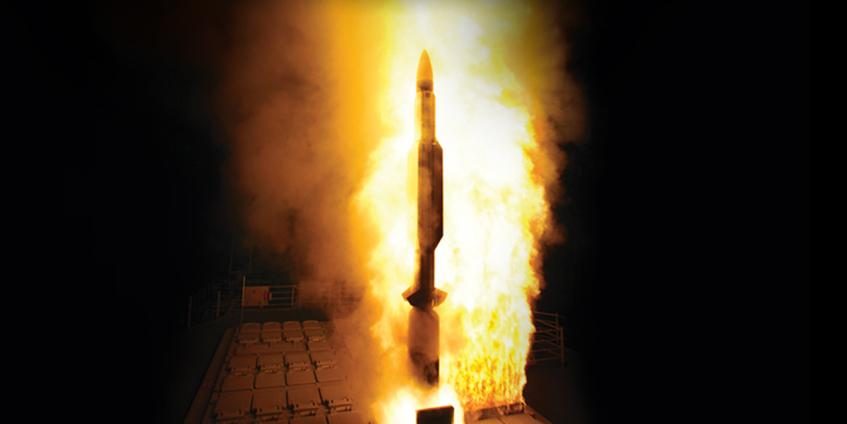
For the past 30 years, shipboard vertical missile launching systems have transformed naval warfare by providing continually evolving launch capability to respond to a myriad of theater-based threats. Unmatched in performance and flexibility, these systems have changed the way all navies think about sea-based missile systems. With the ability to simultaneously respond to multiple aerial, surface, and submerged threats, the vertical missile launching system has become the aspiration of navies around the globe.
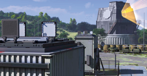
And the future of vertical missile launching systems appears even brighter. Recent advances in ballistic missile defense technology have introduced a new and expanded role for the U.S. Navy’s Vertical Launching System (VLS). With repeated successful intercepts of increasingly complex targets, the U.S.-developed Aegis Weapon System, which includes a radar, weapon control system, VLS, and several classes/families of missiles, has redefined maritime strategy. In addition to performing the traditional navy-specific missions of air, surface, and subsurface defense, many of the newer Aegis-equipped ships are being built or upgraded with ballistic missile defense (BMD) capability. The Aegis BMD capability has proven so successful that it has even precipitated new U.S. BMD policy, including President Obama’s recent decision to leverage Defense investments by adopting a phased adaptive approach to BMD [1]. This approach entails the hybridization of sea- and land-based missile defense systems built upon the Aegis system. This new land-based version of the Aegis has been branded with the moniker “Aegis Ashore.”
This article provides a brief history of the U.S. Navy VLS followed by a “how it works” functional description of the system architecture. Industry efforts to leverage investments and further expand the capability of the VLS are also discussed. The article concludes with several thoughts for future research and development (R&D), including an idea that may offer additional life cycle cost reduction opportunities.
HISTORY
The concept for a ship-based vertical missile launching system was first conceived to support the air defense systems of U.S. Navy surface ships equipped with guided missiles. This concept involved designing a modular, below-the-deck system that would be capable of storing and launching an encanistered Standard Missile (SM), a key armament of the Aegis Weapon System. The below-the-deck design was envisioned to support a greater density of 360° hemispherical firepower with significantly reduced mechanical movement when compared with legacy rotating guide-arm launchers, such as the system pictured in Figure 1. To this day, the advantages of maintaining a below-the-deck missile magazine and launching system have gained such widespread appeal that several domestic and international variants of the VLS concept exist to accommodate a variety of guided missiles of varying size and capability. The U.S. Navy designated the first U.S. surface ship VLS as the Mark (Mk) 41.

Figure 1: Rotating Guide-Arm Missile Launcher.
The Mk 41 VLS was conceived to be built upon a standardized rectangular configuration. While the modular configuration allowed some degree of mission and hull design flexibility, the launchers were essentially designed as forward and aft centralized missile magazines, as pictured in the Ticonderoga-class guided missile cruiser (CG) USS Lake Champlain (CG 57) of Figure 2. U.S. Navy CGs are large combat vessels that operate primarily in a Battle Force role. The ships are designed for multi-mission air, sea, submarine, and land warfare and typically support carrier battle groups and amphibious forces or operate independently or as flagships of surface action groups. CGs were designed to accommodate eight forward and aft modules, and each module was designed to accommodate missiles housed in environmentally sealed canisters. Under normal launch conditions, both the launchers and canisters are designed to be serviceable and reusable.
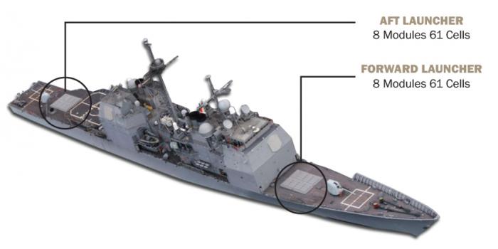
Figure 2: Ticonderoga Class Guided Missile Cruiser USS Lake Champlain (CG 57)
For air defense, the U.S. fleet is equipped with a Mk 41 VLS designed to support the launch of SMs. This capability continues to be upgraded, including the ability to launch new, improved variants of the SM and the Enhanced Sea Sparrow Missile (ESSM). The Vertically Launched Anti Submarine Rocket (ASROC or VLA) provides submarine defense. And for long-range land attack missions, the U.S. fleet is equipped with Tomahawk-missile-launching capability. International variants of the Mk 41 VLS can have nearly identical capability but are generally configured to meet the specific needs of the respective international navy.
Rearming at Sea
The early Mk 41 VLS designs supported a requirement to be able to replenish expended missiles while out at sea. To facilitate this requirement, early MODs of the Mk 41 VLS included the collapsible and storable strike-down crane pictured in Figure 3. While spirited debates persist to this day regarding the necessity to replenish at sea, the crane was ultimately determined to be impractical and, in some instances, dangerous to use, especially with the larger and significantly heavier Strike canister of the Tomahawk Land Attack Missile (TLAM) and SM2 Blk IV missile. Consequently, the strike-down crane is no longer offered as part of the system, and it continues to be removed from the Ticonderoga class ships.
There remains a common misconception that the reclaimed magazine space is available for additional missile launching capability, boosting CG missile storage capacity from 122 cells to 128. In fact, this perceived capability does not exist. When the strike-down crane is removed, the opening is simply sealed with a metal plate that is welded to the deck, as pictured in Figure 4 [3]. When a warship equipped with a Mk 41 VLS runs out of missiles, it returns to a port where expended canisters are removed and loaded canisters are installed with land-based cranes, such as the operation pictured in Figure 5.
Since the inception of the Mk 41 VLS concept, the U.S. Navy has yet to become engaged in a sustained maritime conflict with an adversary of comparable or atypical capability that would have required replenishment at sea. And considering contemporary financial constraints, which could result in a decrease in the number of available guided missile ships and corresponding missiles on station, the debate may continue to linger a bit longer until the policy/strategy is ultimately tested (or changed) or until guided missiles simply become obsolete.

Figure 3 (left): VLS Strike-Down Crane. Figure 4 (middel): Removed VLS Crane. Figure 5 (right): Rearming the VLS.
Figure 6: Arleigh Burke Class Guided Missile Destroyer USS Milius (DDG 69).
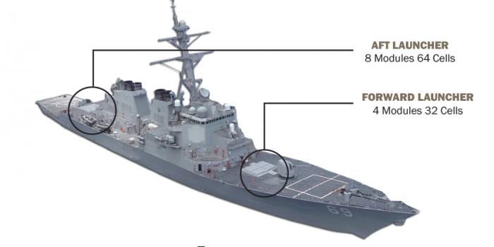
The Aegis Weapon System was fully integrated for sea-based operational testing and evaluation onboard the USS Norton Sound in the early 1980s. And in 1986, the USS Bunker Hill became the first commissioned ship in the Ticonderoga class of U.S. Navy warships to receive the production version of the Mk 41 VLS. Today, modernized Ticonderoga-class warships maintain nearly comparable guided missile combat capability to the newer Arleigh Burke-class of guided missile destroyers, such as the USS Milius (DDG 69), pictured in Figure 6. As the primary Mk 41 VLS platforms for the U.S. Navy, each ship class was designed to serve evolving military roles with regard to vertical missile launch capability. But in terms of maximum load-out, the CGs can support a maximum canister load of 122, compared to the 96 maximum canister load of the DDGs. In addition to serving the U.S. Navy, the Mk 41 VLS is also serving 12 other international navies on a variety of ship classes [2].
The basic foundation of the Mk 41 VLS is the eight-cell module, which can be installed in a ship in any desired number to meet specific mission and hull requirements.
Mk 41 VLS is currently deployed in 13 different configurations, ranging from a single module to 16 modules. The basic module is currently available in two lengths: Strike and Tactical. The U.S. fleet employs the Strike module, which is approximately 25 ft (7.6 m) tall and capable of launching the largest SMs, such as those used to support sea-based, mid-course BMD and long-range tactical strike missiles, such as the Tomahawk. The Tactical module is approximately 22 ft (6.7 m) tall and capable of accommodating the same missile types as the Strike, with exception to the Tomahawk and SMs used for BMD [2]. Lockheed Martin no longer tenders the smaller 17-ft (5.2 m) Self-Defense module because it cannot accommodate the ESSM Block 2 [4].
A similarly configured international version of the U.S. VLS is the Sylver (SYstème de Lancement VERtical) designed by the French company Direction des Constructions Navales S.A. (DCNS). This launcher also comes in several variants, each designated by its height. The A-35 and A-43 VLSs were developed for launching short-range surface-to-air missiles; the A-50 VLS was developed for the longer-range Principal Air Missile System (PAAMS); and the A-70 VLS was developed for larger missiles, such as a land attack cruise missile. The designation numbers refer to the approximate length (in decimeters) of the missile that can be accommodated. For example, the A-43 VLS can hold missiles that are up to 4.3 m long, while the A-70 VLS can accommodate missiles up to 7 m long [5].
Similar to the Mk 41 VLS, the Sylver VLS is configured in eight-cell rectangular modules, except for the A-35, which is also available in a four-cell module. The Sylver can also accommodate missiles that are quad-packed in a single cell or canister, much like the U.S. quad-packed ESSM. However, unlike the Mk 41 VLS, which uses a common plenum and uptake to expel rocket exhaust gas, the Sylver reportedly uses a cell-based modular composite uptake system [6]. The primary air defense weapon used by the Sylver VLS is the Aster missile, which is similar to the U.S. SM.
The U.S. Navy’s next-generation multi-mission guided missile destroyer is the Zumwalt-class destroyer, pictured in Figure 7. The Zumwalt is also designated as a DDG but with the hull numbering system starting at 1000 (i.e., DDG 1000 is the first ship of the class). Designed with the latest technology, the Zumwalt-class destroyer uses a completely different VLS architecture and hot gas management system. Designated as the Mk 57 VLS, the launching system is configured around the periphery of the ship instead of in forward and aft centralized magazines, as is employed with the Mk 41 VLS on current CGs and DDGs.
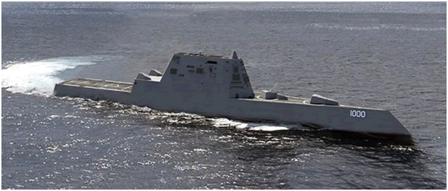
Figure 7: Newest Class of U.S. Guided Missile Destroyers USS Zumwalt (DDG 1000).
MK 41 SYSTEMS DESIGN
Since the mid-1980s, the Mk 41 VLS has maintained a consistent mechanical structure built around the eight-cell modular structure, while the system electronics have been continuously upgraded. The upgrades have incorporated new missile integration capabilities, mitigated obsolescencence, and leveraged the benefits of commercial-off-the-shelf (COTS) components and open system computing architectures, all with the goal of improving systems performance while reducing the systems life cycle cost. The primary system components of the Mk 41 VLS include two Launch Control Units (LCU), one to 16 eight-cell modules with respective module electronics, and encanistered missiles. For each launcher, forward or aft, and regardless of the number of installed modules (between one and eight), there are 400-Hz and 60-Hz power distribution units to supply power to the launcher electronics. Additional launcher support items (e.g., lights, phone, power receptacles, etc.), system transformers, and a Damage Control Junction Box (DCJB) are also provided. Outside the secured launcher area, there is a remote Launch Enable and Status Panel. The Mk 41 VLS also comes with an entire complement of ancillary equipment used for land-based and shipboard testing and maintenance.
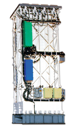
The Baseline VII Mk 41 VLS, pictured in Figure 8, was purposefully designed to support a common modular architecture with a high degree of commonality and interchangeability. Any component of any launcher module can be interchanged with any other launcher module. This choice in architecture adds significant performance in operational availability, survivability, and versatility while minimizing staffing and training requirements. Because the system was designed to accept any missile in any cell, the Mk 41 VLS can simultaneously accommodate multiple weapon control systems (WCS) for the respective missiles of every warfighting mission area—anti-air warfare (AAW), including ballistic missile defense, anti-submarine warfare (ASW), and anti-surface warfare (ASuW). Additionally, to facilitate fast response to multiple diverse threats, the Mk 41 VLS can simultaneously prepare one missile in each half of a launcher module and can also fire a four-missile salvo of ESSMs from one canister.
Figure 8: Baseline VII Mk 41 VLS Module.
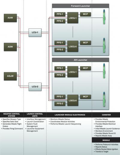
The functional allocation of the latest Mk 41 VLS design is illustrated in Figure 9. AAW, ASW, and ASuW missions are initiated from their respective WCSs, where intent-to-launch commands are generated. These commands are routed to two LCUs located in two different Combat System Equipment Rooms (CSERs). During normal operations, each LCU controls half of the missile launchers in any ship. However, when in a causality mode, ether of the LCUs can control all the launchers. Each LCU communicates with all WCSs. The LCUs are responsible for managing launch history, inventory, missile availability, and selection. Depending on the mission, when the LCU is commanded to select and fire a missile, the respective LCU selects the appropriate missile from launcher inventory and then coordinates launch activity with the Launch Sequencer (LSEQ) of the missile to be launched. The LSEQ checks for hazards and initiates the launch sequence. A typical launch sequence consists of checking for hazards; turning power supplies on and off; and energizing and operating relays, motor hatches, and plenum drains.
Figure 9: Functional Allocation of the Baseline VII Mk 41 VLS.
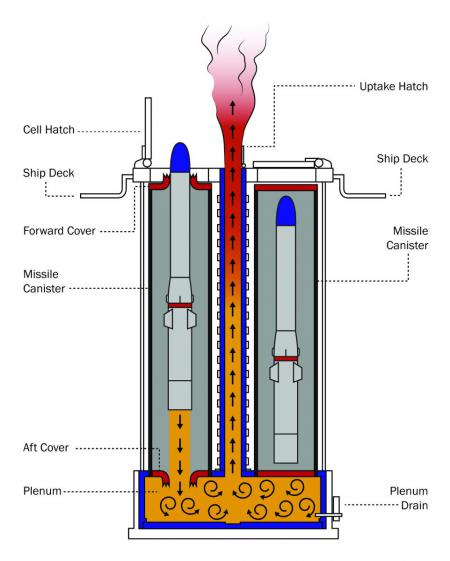
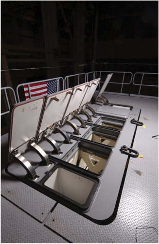
The VLS module, consists of an upright structure that provides vertical storage space for eight missile canisters. A deck and hatch assembly at the top of the module protects the encanistered missiles during deployments. Generally, the hatches are only opened to perform maintenance or to permit missile launches. The plenum and uptake structure capture and vent hot missile exhaust gases vertically up through the module to the atmosphere through the uptake system, as illustrated in Figure 10.
Figure 10: Mk 41 VLS Hot Gas Management System.
Electronic equipment mounted on the eight-cell module coordinates and performs the launch of missiles. The latest Mk 41 VLS design is designated as Baseline VII. For each module, the electronics consist of an LSEQ, Motor Control Panel (MCP), and two Programmable Power Supplies (PPS). Because the missiles are launched from centralized magazines, where missiles are stored inches apart, the management of rocket motor exhaust gas is critical for ship safety and launcher maintainability.
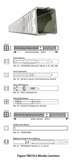
A Status Panel is located outside of the launcher magazine to receive and display the status of all launcher modules and all hazard signals from within the launcher. The panel also routes this information to the ship’s command station. Most importantly, the Status Panel manages the launch enable command, which is required to enable the launch of a missile. Storage, shipping, and integration of weapons is facilitated with environmentally sealed and canersterized missiles. To support the requirement for long-term storage, the canisters are equipped with desiccant. The canisters are designed to accommodate the variety of missiles illustrated in Figure 11. While the length of a missile can vary significantly, all canisters maintain a common 25-in square form factor with a common 145-pin electrical connector interface to the launcher. Forward and aft end covers provide environmental seals for the missiles. The aft cover is ruptured at rocket motor ignition, which also generates an electrical signal to inform the weapon system that the rocket motor has in fact ignited. Almost immediately after rocket motor ignition, the restraint bolts are blown and the missile begins to egress the canister by physically penetrating the forward cover. In the event the restraint bolts do not release the missile after rocket motor ignition, an overtemperature sensor confirms the restrained launch and activates a water deluge of the canister. The deluge system pumps fresh water into the canister to cool the system, and if the temperature does not decrease sufficiently, the system continues to pump in sea water until it does. The water is removed from the launcher module plenum via a controlled drain.
Figure 11: VLS Encanistered Missiles.
The more recently designed Mk 57 VLS, pictured in Figure 12, employed by the Zumwalt-class destroyer is also intended to maximize the flexibility and adaptability of the shipboard weapon systems by employing electronics and software that use an open computing architecture. Conceptually similar in construction to the Mk 41 VLS, the Mk 57 VLS is assembled with identical four-cell modules, which can use the current inventory of Mk 41 encanistered missiles and potentially even larger missiles. Unlike the Mk 41 VLS, the Mk 57 VLS was designed to be installed on the ship periphery instead of in centralized magazines. The Mk 57 VLS functional architecture is partitioned into four primary assemblies that manage and maintain the missile inventory and launch functions [6].
Figure 12: Mk 57 VLS.
The Canister Electronic Unit (CEU) provides the “any-missile-in-any-cell” capability required by Navy VLSs. The CEU connects to an encanistered missile, interfacing the missile with the ship’s combat system. In essence, the missile is simply a client on the weapons systems network. A Module Controller Unit (MCU) is provided to manage the launcher module and launcher equipment, monitor missile and canister activity, and detect and report faults and hazards. The transfer and monitoring of ship power to both the launcher and the missiles is provided by the Power Distribution Unit (PDU). And a Hatch Control Assembly (HCA) provides the motion and motor drive control required to actuate the launcher’s missile and exhaust hatches.
The Mk 57 VLS employs a gas management system that is a departure from the gas management system of the Mk 41 VLS. The Mk 57 reportedly uses a U-shaped gas management system that facilitates the egress of rocket motor exhaust gas through the uptake while mitigating the flow of hot gas into adjacent cells and the reversed flow into the active cell. This new gas management design is reported to be capable of accommodating new missile designs having up to a 45% greater rocket motor mass flow rate than rocket motors currently in use in U.S. VLSs. A reported advantage of this design is the elimination of a missile deluge system such as the system used in the Mk 41 VLS [8]. Elimination of the deluge system not only reduces maintenance requirements; it also eliminates the risk of an inadvertent deluge of a missile.
FUTURE TRENDS
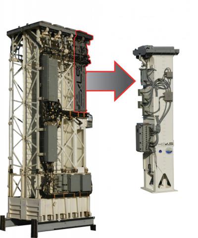
Industry attempts to leverage R&D investments in both the Mk 41 and Mk 57 VLSs are ongoing. For example, an endeavor pursued by Lockheed Martin includes integrating nontraditional missile classes into the Mk 41 and Mk 57 launchers. The ExLS, pictured in Figure 13, fits within the volume of a standard VLS cell and incorporates a munitions adapter that mechanically retains multiple smaller munitions in a qualified All-Up-Round (AUR) configuration. The ExLS reportedly supports its own launch sequencing electronics and power supplies and has the ability to interface directly with the launch control computers of either the Mk 41 or Mk 57 VLSs [7]. The system appears to be marketed as a capability that can be dropped into existing launchers, but it is not clear how new physically integrated weapons will work with the legacy weapon control systems of CGs and Arleigh Burke/Zumwalt DDGs without the need for significant modifications to the existing weapon control system or a new system altogether.
Figure 13: Lockheed Martin ExLS.
In any case, defense contractors Lockheed Martin and MBDA remain bullish and are pursuing efforts to integrate European missiles in the US Mk 41 VLS. The team recently demonstrated the ability to integrate and launch a European naval variant of the Common Anti-Air Modular Missile (CAMM), or Sea Ceptor, in a Mk 41 equipped with the ExLS. In this demonstration, the Sea Ceptor was cold-launched, as pictured in Figure 15, from its own canister with a gas ejection system and launch sequence that bypassed the commonly used Mk 41 LSEQ. Such a development is welcome news to the growing number of international navies employing the Mk 41 VLS, as this capability may provide the needed flexibility to use missiles from different countries.
Another Lockheed Martin effort to leverage previously developed Mk 41 VLS technology was the development of a Single Cell Launcher (SCL). The SCL, pictured in Figure 14, maintains the form factor of the Mk 25 Quad Pack ESSM canister with a modified scalable mechanical structure. This design provides additional flexibility for smaller platforms, such as frigates, patrol ships, and corvettes, where the size and weight of a traditional launcher module are of concern [8]. In fact, as pictured in Figure 16, Lockheed Martin has recently developed a concept for installing four SCLs in the Freedom Class Littoral Combat Ship (LCS) to enhance its combat capabilities.
 |
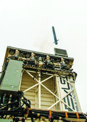 |
| Figure 14: Lockheed Martin SCL. | Figure 15: Cold Launch. |
Figure 16: Freedom Class LCS with SCL Concept.
Cold Launch Vs. Hot Launch
The VLS “cold launch vs. hot launch” debate has been gaining new momentum in recent years. Both system designs have their advantages and disadvantages. Hot launch systems have much faster engagement times as the missile is released from the ship almost immediately after the motor is ignited, whereas with a cold launch system, the missile must first be ejected from the launch cell and then ignited, thus extending the launch time. Further, cold launch systems do not require a hot exhaust gas management system but do require a gas, piston, or elevator ejection system, which could introduce additional mechanical reliability concerns. The primary hazard with hot launch systems is the risk of a restrained firing (i.e., the missile rocket motor is ignited, but the restraint bolt[s] do not release). Likewise, cold launch systems have the risk of ejecting the missile without subsequent rocket motor ignition, potentially resulting in the ejected missile falling back onto the deck of the ship.
In either case, new hot/cold hybrid VLSs have gained renewed interest in both the United States and Europe. The feasibility of such a system was recently demonstrated by Lockheed Martin and MBDA when a Common Anti-Air Modular Missile (CAMM), or Sea Ceptor, was cold-launched from the Mk 41 VLS (pictured in Figure 15) using the Lockheed Martin Extensible Launching System (ExLS).
Nearly 90% of the SCL’s components are common with the Mk 41 VLS, which should reduce the technical and logistical support burden and thereby minimize the overall life-cycle cost. And the SCL has been fully qualified for both performance and safety, including completing a demonstration of the system’s ability to mitigate the hazards of a restrained firing.
In a more recent development, the Missile Defense Agency and the U.S. Navy successfully demonstrated the Department of Defense’s (DoD’s) ability to reuse and repurpose an existing tactical system to perform a new mission. In May 2014, a BMD test was performed using a land-based variant of the Navy’s Aegis Weapon System currently deployed on board certain ships. As mentioned previously, the system, called “Aegis Ashore,” successfully fired a Standard Missile-3 Block IB guided missile from an Mk 41 VLS. The interoperability of Aegis systems should enable sea- and land-based systems, as illustrated in Figure 17, to work in concert to extend BMD coverage. Given the long, successful history of the Aegis system—and the fact that the system is currently in production and supporting both U.S. and international navies—the implications of the Aegis Ashore system demonstrating the same effectiveness as the sea-based system without having to invest in a new land-based system could be game-changing.
Figure 17: Aegis Ashore Concept.
CONCLUSION
While the successes of the Mk 41 VLS could never be overstated, efforts to improve system performance while continuing to reduce life-cycle cost must be the focus for the foreseeable future. The incorporation of “open” computing architectures into such systems has been, and continues to be, a necessary first step. But it’s only a piece of the VLS cost puzzle, and additional standardization and COTS utilization is essential for further cost reductions. Much of the attention has been focused on ensuring the latest variants of the weapon and launch control computing and communication environments leverage COTS technology and employ open computing standards. However, when it comes to launcher electronics and the respective communication interfaces, the incremental advances that have been made remain incomplete.
Updating and standardizing the communication interfaces between the launch sequencer electronics and the missiles might be a logical next step. While this may be a difficult near-term investment, it may be necessary to realize significant cost savings in the future. For example, the current umbilical cable to the missile canisters is a historical compilation of different custom communications protocols from RS- 232 to Mil-Std-1553, which generally only serve one missile class. Perhaps standardizing all U.S. Navy missile communication interfaces to a single protocol should be further analyzed. The latest Mk 41 VLS baseline design modularizes the launch sequence electronics to an individual cell. These electronics modules, which use the PC/104 embedded computer standard, are referred to as Cell Control Modules (CCM); and each is configured as a client in the missile launching network. The Baseline VII Mk 41 configuration has significantly improved COTS usage and missile availability, but each CCM still has a custom missile interface card for each missile class. And every umbilical to every missile canister remains bloated with a variety of missile communication interfaces regardless of the missile in the canister. Employing a standard missile communication interface would open the manufacturing of the electronic modules to more commercial competition while mitigating continuous issues with electronics obsolescence. Commercial industry could be positioned to more cost effectively manufacture generic electronic launch control modules and manage electronics obsolescence issues, allowing DoD contractors to focus on the more sensitive control software. With around 100 CCMs (including onboard repair parts) on a single DDG, the hardware savings could add up quickly.
References:
- U.S. Department of the Navy. “US Navy Program Guide 2014.” Washington, DC, 2014.
- Lockheed Martin Corporation. “Mk 41 Vertical Launching System.” Company brochure, Washington, DC, 2013.
- Callinan, C. Personal Communication. Lockheed Martin Corporation, Fleet Support, 19 June, 2014.
- Ciappi, J. Personal Communication. Lockheed Martin Corporation, Business Development, 8 August 2014.
- Direction des Constructions Navales S.A. “Sylver.” Company brochure, Paris, France, 2010.
- Raytheon Corporation. “Mk 57 Vertical Launching System.” Company brochure, Tewksbury, MA, 2007.
- Lockheed Martin Corporation. “Extensible Launching System.” Company brochure, Washington, DC, 2010.
- Lockheed Martin Corporation. “Single Cell Launcher.” Company brochure, Washington, DC, 2014.


