BACKGROUND
Various Department of Defense (DoD) modeling and simulation (M&S) groups perform digital and hardware-in-the-loop (HITL) threat missile flyout and hit point analyses to assess weapon effectiveness and platform susceptibility (and ultimately survivability) based on signature models derived using either organically developed tools and processes or those available from other government, industry, or academic sources.[1] However, many of the contemporary government tools for prediction of aircraft engine exhaust signatures were developed when lack of processing power and similar reasons required the developers to use simplified lower-fidelity methodologies to achieve solutions in a reasonable time. Such is the case with the original F-16C engine exhaust plume signature model, a simplified variant of the original missile-oriented Standard Plume Flowfield (SPF)[2] code. The SPF code was incorporated into the Spectral and In-band Radiometric Imaging of Targets and Scenes (SPIRITS)[3] signature generation code to provide the aircraft plume mixing between a principal core exhaust and the surrounding freestream in support of infrared (IR) signature predictions. While this approach was reasonably suited for the plume modeling of B-52 turbojets within a limited range of flight conditions, its predictive limitations for other aircraft systems became increasingly apparent in the early 1990s as the importance of internal turbofan augmentor/nozzle mixing and downstream shock trains on plume IR signature accuracy was recognized. When attempting to extend these models to rotorcraft, the application is even more limited, especially given the earlier codes’ basis on isolated, round nozzle configurations with legacy engine exhaust thermal barrier coatings of consistent, highly diffuse, and high-emissivity behavior.
Historically, the use of these tools can lead to poor predictions of plume spatial and radiometric characteristics as well as plume impingement heating on aircraft surfaces when performed for higher angles of attack or for airframe designs that include advanced exhaust system configurations (e.g., rectangular nozzle geometries, serpentine exhaust paths, highly integrated engine-airframe installations, and efficient plume mixing enhancement devices). This fact, in turn, impacts the ability to properly generate scene and signal information to support both digital and HITL modeling and performance assessment of various electro-optical/ infrared (EO/IR) sensors and associated systems, such as weapon seekers, guidance and navigation control loops, missile warning systems, countermeasure/counter-countermeasure (CM/CCM) systems, etc. These issues are exacerbated as sensor technologies evolve and take advantage of improvements in resolution, sensitivity, and imaging capabilities. Models that can more fundamentally address these nonaxisymmetric, high-aspect ratio geometries, along with their inherently more complex mixing physics, within reasonable computational timeframes and that can be integrated into the existing M&S process would certainly lead to more reliable predictive capabilities, development of better flow path configurations, and improved weapon effectiveness and platform survivability assessments.
Attempts to improve aircraft plume modeling capability using more advanced Navier-Stokes flow solvers, however, were initially hindered by difficulties in their operational usage and long solution runtimes; these factors limiting their acceptance by the modeling community in favor of quick-fix, ad hoc approximations to correct observed signature prediction deficiencies, which usually result in other issues such as poorer correlation of spectral data. Fortunately, advancements in modern computer hardware technology, along with development of improved flow algorithms, have enabled the development of fast-running and highly accurate heat transfer and computational fluid dynamics solvers that can support the IR signature M&S requirements needed to support modern weapon system assessments.
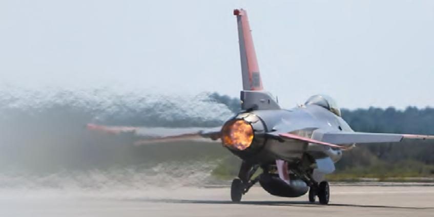
With this in mind, the Guided Weapons Evaluation Facility (GWEF)[4] in collaboration with the QF-16 System Program Office (SPO),[5] both located at Eglin AFB, FL, and supported by the SURVICE Engineering Company[6] and Combustion Research And Flow Technology (CRAFT Tech)[7]—have undertaken an initiative to improve both fixed-wing and rotary-wing aircraft exhaust plume signature modeling in terms of fidelity and spectral/spatial characteristics and integrate the developed code and methodologies into accepted DoD aircraft signature and scene generation tools. The initial programs/ platforms selected for development and validation of the M&S tools and processes through incorporation during their assessments were the QF-16 (fixed-wing) and UH-60M[8] (rotary-wing) (Figure 1).
![Figure 1: QF-16 Exhaust Nozzle (left [2014© William Schenck]) and UH-60M with UES Aft of Main Rotor Hub (right). Figure 1: QF-16 Exhaust Nozzle (left [2014© William Schenck]) and UH-60M with UES Aft of Main Rotor Hub (right).](/wp-content/uploads/2019/11/aircraft-engines-figure-1.jpg)
Figure 1: QF-16 Exhaust Nozzle (left [2014© William Schenck]) and UH-60M with UES Aft of Main Rotor Hub (right).
The QF-16 program was a relatively new start program at the GWEF. That, along with the requirement to model three engine variants (the F100-PW-200D, F100-PW-220E, and F110-GE-100B) and a robust ground and flight test data collection program, allowed fidelity studies to be performed on the impact of various mixing devices within the flow path. Development and verification of the QF-16 model also took advantage of the latest FLIR™ state-of-the-art electrically cooled MWIR and LWIR imaging sensors, as well as the first field-usable hyperspectral imager manufactured by Telops™ for collection of ground and in-flight data for model correlation and verification. This spectral imaging capability, owned by the 782 TS/ RNWI Instrumentation Branch at Eglin AFB, FL,[9] provides the ability to verify and validate (V&V) models to measurements quickly and accurately since the target can be seen spectrally without any assumptions to boresighting setup. Additionally, since spectral information for each individual pixel of the image is collected, each image can be separated into distinct frequencies as well as composited across a user-specified bandwidth using image/spectral processing tools developed by RNWI. The hyperspectral imager has been integrated into RNWI’s post-processing methodology using the standard FLIR SAF file format, which provides data product end-users a self-extracting data and tool product. This product is a significant benefit, especially in DoD classified processing environments, where getting approval for the installation of unapproved software can be a rigorous process.
The UH-60M program, on the other hand, was an effort already under way that afforded an opportunity to assess the efficacy of merging advanced commercial modeling techniques into a typical DoD production model development cycle (with respect to data analysis and correlation, cost, schedule, etc.), where model verification could be performed against tried-and-true dewar-cooled single-band MWIR sensor data that had already been collected and verified by both the Government and the engine original equipment manufacturer (OEM). The UH-60M, configured with the T700-GE-701D engine, is particularly challenging due to the dual upturned exhaust system (UES) and exhaust mixing with the main rotor downwash. However, this system is not atypical of exhaust signature suppression techniques that could be expected to be employed on current and future rotorcraft platforms.
More succinctly, the primary difference in the paths taken with the two programs is that the QF-16 effort required new analytical processes and codes as well as measurement process advancements related to fixing issues with DoD legacy models, whereas the UH-60M effort had access to multiple high-quality existing datasets, allowing modeling issues to be addressed largely with advanced COTS codes.
M&S PROCESS IMPROVEMENT
As part of the QF-16 SPO’s efforts to field the next-generation air superiority target, IR and RF signature model development is a key component to fully support future missile and sensor programs. As such, they conducted numerous meetings and discussions with the GWEF, engine OEM aerothermal analysis subject-matter experts (SMEs), and industry personnel with expertise in the development of both proprietary and DoD aircraft hot parts and exhaust plume signature codes. The conclusion was that better modeling methodologies and tools would be needed to address the aforementioned issues and their specific requirements to ensure the capability to support current advanced and future weapon systems.
In that context, efforts were sponsored to improve QF-16 IR signature M&S, leading to improvements in the target scene inputs feeding digital and HITL simulations for the assessment of CM and weapon system effectiveness. The implementation of these efforts improves predictive results for all phases of the weapon engagement process, from search and acquisition to tracking throughout flyout to endgame response and hitpoint assessment. Key to this is the ability to create a relatively fast, but highly accurate, flowfield with three-dimensional effects of swirl and multi-stream mixing phenomena, as well as nozzle internal geometry effects. In other words, a large range of realistic nozzle characteristics would need to be simulated. Typically, this level of simulation is not performed in DoD M&S; it is usually performed only at the OEM level during the design and manufacturing process using codes normally not available to the DoD. (And, even if these simulations were run, they would generally not be suitable for use during the normal acquisition process due to the long run times.) Moreover, the process would have to be workable within the framework of the current M&S process (as shown in Figure 2) (with the modern modifications to the process shown within the dotted lines), while keeping in mind the need to simultaneously reduce the time and cost normally associated with the process.
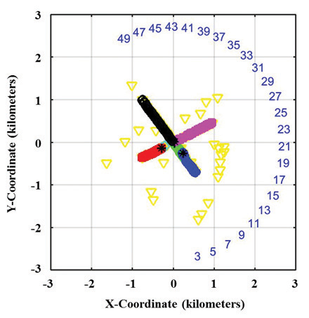
Figure 2: Insertion of High-Fidelity QF-16 Plume Modeling Methodology into Legacy DoD Process.
The typical signature process begins with standard engine cycle deck output parameters and use of tools such as TRBEXT (a module within SPIRITS) to describe the core gas flow stream (mass flow rate, pressure, and temperature), as well as fuel consumption rate for use as boundary conditions in a subsequent flowfield generation code. Exhaust species compositions are usually based on a complete combustion assumption and a uniform exhaust exit profile, which is not generally the case. For hot parts, exhaust component temperatures, which are directly related to the exhaust flow, must be calculated. This calculation requires an understanding of the film cooling effectiveness metric, which is dependent on the various cooling methods employed (usually either slots or cooling holes). The metric is generally known only to the engine manufacturer. To overcome this, various methods have been used to approximate these hot part temperatures; however, they still have insufficient accuracy and require the analyst to make considerable assumptions and rely heavily on measured data, which may not be available, for correlation and corrections. In the UH-60M modeling process, conjugate heat transfer with the computational fluid dynamics (CFD) solution based on advanced commercial codes could be used as a starting point, and final adjustments could be made by the aerothermal analyst through verification of the model to the available measured data.
A problem arises in that this particular methodology can be stressed when developing models that employ engineered cooling flow features using an active method to draw cooling air from the engine cycle for use in reducing the temperature of hot parts in the exhaust flow path, as is the case with the F-16. This can be addressed by inserting thermocouples into exhaust system hot parts to collect temperature data within the field-of-view of the measurement sensing equipment and application of a general understanding of the reflective properties of the hot part surfaces to determine actual hot part metal temperatures vs. apparent temperatures. This method is used regularly by both the airframe and engine OEMs and has been incorporated into the QF-16 modeling process by installing thermocouples, with assistance from the engine OEM, in one of the divergent seal segments of the variable geometry exhaust nozzle and measuring the bidirectional reflectance distribution function (BRDF) of the coating on the exhaust nozzle segments) using a Surface Optics SOC-400 field portable reflectometer provided by RNWI.
Once the necessary data were in hand, fundamental research was needed to develop a SPIRITS fast running plume solver module that could provide highly accurate results for the various engine flow path configurations across the necessary flight conditions. The inclusion of a true Navier-Stokes methodology in the critical first several meters (user adjustable) of the plume—combined with a faster, although less accurate, parabolized Navier-Stokes method on the less critical (less hot) sections of the plume—worked very well. The QF-16 program succeeded in that CRAFT Tech and SURVICE were able to create a relatively fast (for CFD) high-fidelity flowfield model that far surpassed the prior DoD model in realism (as verified through correlation to both ground and flight test data). Features of the new SPIRITS F-16 plume module include direct modeling of the internal core/ fan mixing starting at the turbine exit, incorporation of afterburning effects, the ability to handle incomplete combustion, shock-diamond and Mach disc capturing, and improved turbulence modeling for high-speed conditions. Moreover, this new plume solver exists as a seamless replacement within the SPIRITS framework without requiring additional user intervention or specialized flow modeling expertise. With today’s multi-core laptops and desktops, these simulations, previously requiring 1 day of dedicated computational effort on a supercomputer, now require less than 1 minute while simultaneously providing improved predictive accuracy.
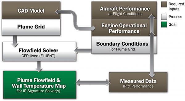
For UH-60M, the method was laid out into the most generic of processes for solving a high-fidelity flowfield. This action was performed to both simplify and provide future extensibility to any available CFD solver. The process is shown in Figure 2.
The methodology in Figure 3 is essentially academic in that the IR model development goal is all about the flowfield. How the analyst gets there is essentially the same for a CFD model: develop the geometry, build the grid, apply boundary conditions from a GFE or OEM engine cycle deck, shove the inputs into a CFD solver code, and then verify the outputs against measured data.
Figure 3: Generic CFD-Based Process as Used in H-60M Plume Modeling.
RESULTS
For the QF-16, the correct modeling of shocks from a fighter engine’s typically under-expanded nozzle setting was important to the program’s direction of improving fidelity. Figures 4 and 5 provide a few examples of the program’s success in incorporation of complex flow path element modeling and accurately predicting plume phenomenology using both of the methodologies discussed previously.

Figure 4: Comparison of Flowfields as Generated by Legacy Process and Modified Legacy Process.

Figure 5: Generic H-60M Process Used to Determine QF-16 Shock Diamond Centroid Locations Across Three Power Settings.
Further, when compared to in-flight test data, the model is providing both the appropriate plume intensities along with correct shock diamond spatial characteristics, as shown in Figure 6.
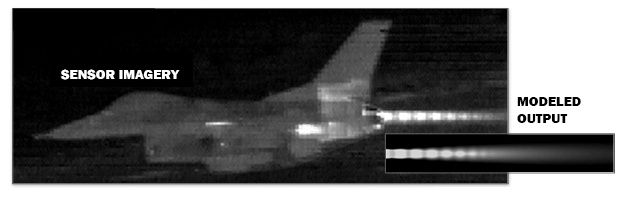
Figure 6: Measurement Sesnor Image Compared to High-Fidelity QF-16 Modeling Process Output.
The QF-16 model is currently under going extensive V&V as newer data collection instrumentation provides plume imagery/radiometric data with several orders of magnitude better resolution using field-capable hyperspectral imagers. In the case of the QF-16 data collection led by the 782nd Test Squadron at Eglin AFB, FL, a Telops hyperspectral imager is being used in lieu of the typically boresighted Bomem spectrometer. Additionally, hot part definition and temperature prediction are more accurately captured with higher-resolution filtered imagery correlated with remotely acquired data using nozzle wall thermocouples, allowing for high-fidelity temperature mapping.
The QF-16 M&S program tasks are also unique in that project limitations will result in no in-flight measurements of the F100-PW200D-powered aircraft. The last test, a ground test for the F100-PW-200D engine, is scheduled for completion in latter 2014, with the data correlations to be performed shortly afterward. Signature in-flight IR performance for that engine variant model will be extrapolated from the ground test measurements of all three engine variants and in-flight measurements for the other two engine variants. The impact of this limitation is minimal, as data taken so far show each variant’s IR performance is consistent with what its respective GFE engine cycle decks, providing confidence that extrapolation to the F100-PW-200D will be a straightforward process.
UH-60M plume development is a similar model in that there is a need for a high-fidelity solution that provides both spatial and radiant intensity correctness. Overlaid onto this requirement were the typical program production-oriented tight constraints on both cost and schedule. In particular, the schedule constraints required that the work be completed in a matter of several weeks vs. the normal process that usually takes many months. Auto-meshing techniques were initially employed that kicked off the needed scene generation object, and the COTS CFD solver, ANSYS Fluent™, was employed to quickly arrive at a workable solution that generally matched the measured data from the dewar-cooled MWIR sensing instrumentation used by the Navy to collect imagery and radiometric data. In this manner, a plume solution was developed and the same CFD solution set was used to generate wall temperatures from the built-in conjugate heat transfer solver within Fluent™. It should be noted that this method of creating the flowfield and acquiring metal wall temperatures is entirely an academic process. Fluent™ was chosen due to the solver’s tight integration with the standard ANSYS™ meshing utility, the numerous available turbulence models, species tracking abilities, and built-in heat transfer analysis capabilities. Additionally, the entire CFD process can be parameterized within the ANSYS Workbench™ environment, yet the output can remain ASCII generic, thus allowing any CFD process to be used.
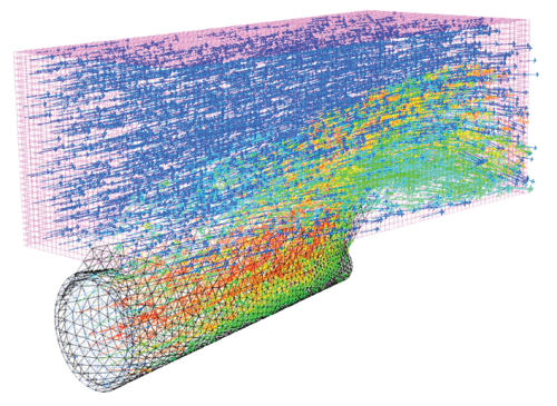
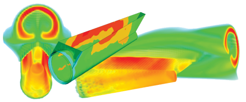
An important aspect to this process, often encountered in V&V of IR models to sensor data, is determining the correctness of the IR contributors; and this problem is generally prolific from the bright exhaust cavity, since as exhaust systems become more complex in their flowpaths, cooling, and materials, the ability to quickly determine the breakout of the major contributors becomes increasingly difficult, often requiring experienced IR analysts to methodically determine and correct problem areas of the IR model. Although HITL time constraints prevented implementation for this particular effort, a CFD grid of the full model as provided was developed to accurately simulate and determine system aspects that would affect signature radiometric values. This is academically depicted in Figure 7 using Flow Vector and Temperature solution output for a notional exhaust system. Thorough modeling is necessary to provide both the realism and accuracy needed to adequately assess modern weapon systems performance within the HITL simulation process. The initial coarse model, as used in this HITL effort, had a mostly isothermal cavity and thus required some fine tuning of the signature values in this area. And in time-honored IR analyst tradition, “assumptions were made” based on comparing the model to the measured data. However, care must be taken as erroneous assumptions can lead to poor results in other areas, such as skewed spectral output. Using a higher-fidelity solution was shown to provide good correlation to the measured data, reducing the need to manipulate model outputs. Here again, we illustrate the solution output in Figure 8 using the simplified mixer-ejector exhaust system. For example, consider the case where spectral data are either incorrect or unavailable; a model that allows accurate simulation of the hot parts temperatures will be more accurate spectrally. This methodology will be implemented for future efforts.
Figure 7: Flow Velocity Vectors and Temperature Visualized on Top of a Predominately Auto-Generated Mesh.
Figure 8: CFD Based Flow and Wall Temperature Mapping for a Notional Turboshaft Mixer-Ejector Exhaust System.
By capturing all propulsion integration and system features for the system, not only did the developed model more closely match known propulsion requirements, but a clearer understanding of the relative magnitudes of the various energy sources within the HITL scene was produced.
CONCLUSION
Both the QF-16 and UH-60M programs successfully developed improved plume signature models that showed good correlation to their respective test data and demonstrated the viability of incorporating the methodologies into the model development process to improve model quality.
The impact of these two modeling processes is incremental and yet profound. Under QF-16, the legacy DoD IR signature modeling process was modified to provide high-fidelity CFD modeling as a seamless option to support exhaust plume modeling, with the impact to the model end user being transparent. UH-60M, on the other hand, bypasses and integrates several of the more time-consuming legacy methods, using commercial-off-the-shelf (COTS) tools in their place. While requiring some extra intervention on the part of the user, the use of COTS CFD and heat transfer solution methods was performed in a proprietary-less implementation, providing for future extensibility to other codes. More importantly, from a production perspective, this new modeling process provides the GWEF a capability to model target exhaust plumes and calculate hot part temperatures at a level equivalent to many OEM specialized codes, with the only possible shortcoming being the availability of input data, such as geometry, cycle deck, and other proprietary data to which the Government may not have access. However, just as proprietary data availability is problematic to the point of routine, the “routine” availability of quality IR measured data is more common and can bypass some of the need for proprietary data, allowing this type of process to succeed within the DoD, where, ironically, it might fail if relied upon in industry. Additionally (and from a business perspective, probably more importantly), this new process allows the GWEF to take better advantage of organic data collection capabilities within the sister 782nd Seekers and Sensors Test Flight and in-house modeling processes to develop high-fidelity models significantly quicker than the lower-fidelity models of the past.
Both programs are still undergoing assessments at the GWEF to determine the impacts to weapon effectiveness and platform susceptibility. It is anticipated that the initiative will provide fundamental improvements to the assessment of advanced platforms, such as the Joint Strike Fighter, in terms of cost and schedule savings and improved data quality.
References:
- Additional information on radiation theory and sources, aircraft IR signature simulation, and EO/IR data collection can be found in the SENSIAC Handbooks Infrared Handbook, Infrared & Electro-Optical Systems Handbook Set, Sources of Radiation, and the SENSIAC SOAR Infrared Signature Simulation of Military Targets.
- SPF-III is a US Government-owned Joint-Army- Navy-NASA-Air Force (JANNAF) computer code used for predicting the gas dynamic structure of single- and two-phase low altitude (<70 km) rocket exhaust plumes and is used to predict plume signatures and plume/vehicle interaction phenomena. SPF-III distribution is provided by The Johns Hopkins University Chemical Propulsion Information Analysis Center (JHU CPIAC), Columbia, MD, cpiac@cpiac.jhu.edu, 410.992.7300. Visit https://www.cpiac.jhu.edu/node/20 for more information.
- SPIRITS is a U.S. Government-owned JANNAF integrated system of computer codes to predict EO (UV, visible, and IR) spectral and spatial data for aircraft hardbody and plumes. SPIRITS distribution is provided by the JHU CPIAC, Columbia, MD, cpiac@cpiac.jhu.edu, 410.992.7300, with release approval from the 782 TS/RNWGH (GWEF), Eglin AFB, FL, Ms. Amenda Amick, mary. amick@us.af.mil, 850.882.9978. Visit https://www.cpiac.jhu.edu/node/20 for more information.
- The GWEF, Eglin AFB, FL, is the DoD’s premier full-spectrum (UV, IR, visible, laser, MMW, traditional RF, and inertial/GPS) digital M&S and HITL test facility for weapons parametric measurements, CM/CCM testing and performance characterization. For more information, contact Mr. Visal Som, 782 TS/RNWGH, visal.som@us.af.mil , 850.882.9978.
- The QF-16 Program Office, Eglin, AFB, FL, is currently performing systems integration and testing of the F-16 as the newest aircraft to assume the unmanned Air Superiority Target role for the DoD. For more information, contact Mr. Clayton Vind, AFLCMC/EBYA, clayton.vind.2@us.af.mil, 850.883.3368.
- The SURVICE Engineering Company provides services in the areas of systems engineering, M&S, test and evaluation, analysis, metrology, and applied technology solutions. For more information, contact Mr. Scott Armistead, scott. armistead@survice.com, 850.362.6920.
- CRAFT Tech specializes in high-fidelity CFD simulation of complex flow and combustion problems. For more information, contact Mr. Neeraj Sinha, sinha@craft-tech.com, 215.766.1520.
- The UH-60M is an upgraded derivative of the UH-60 helicopter featuring improved payload, digital cockpit displays, strengthened fuselage, composite spar wide-chord blades, and more powerful engines (T700-GW-701D). For more information, Mr. Keith Hilliard, 256.842.4436/ 256.541.1775 (bb).
- The 782nd Seekers and Sensors Test Flight provides instrumentation development and data collection and analysis support activities, for DoD T&E activities including both red and blue missile performance, aircraft self-protection systems, and threat system performance in support of aircraft and surface target survivability studies. The Test Flight’s extensive target signature measurement capability provides calibrated broadband, spectral, and hyperspectral data across the full electromagnetic spectrum in operational environments. For more information, contact Mr. Rusty Bauldree, Chief, 782 TS/RNWI, 850.882.5602, russel.bauldree@us.af.mil.


