


Introduction
All ammunition makers and reloaders “know” that changing propellant type can affect the group size (dispersion) of the ammunition they make. Why changing powders affects bullet group size is more than a matter of propellant burnout prior to muzzle exit or some other easily definable characteristic. This article details the investigations undertaken to better understand this phenomenon and why it occurs.
Background
Prior to this study, it was observed that powder simply provided the “push” for bullets if the propellant met the following conditions:
- Burned out prior to shot exit.
- Provided the desired muzzle velocity within the established pressure limits.
- Exhibited low muzzle velocity variation.
As a result of this study, it has been shown that propellant can also have a dramatic effect on group size.
Figure 1 shows the initial angle of attack (α) and the initial angular rate (ω) of the projectile at muzzle exit, exaggerated for clarity. The initial angular rate (ω) at muzzle exit is responsible for most of the short-range dispersion exhibited by small-caliber projectiles. The interaction between the flexible projectile and the flexible, nonstraight barrel bore is the source of the projectile’s initial angular rate.
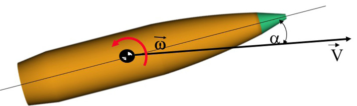
Figure 1. Initial Angle of Attack and Projectile Angular Rate (Source: J. Siewert).
Variations in barrel pointing and translational velocity at muzzle exit also contribute to dispersion but generally to a much lesser extent.
A limited set of dispersion data was provided by Hornady Manufacturing Company on their 6.5-mm, 140-gr (extremely low drag – match [ELD-M]) projectiles using various propellant types. This projectile was selected because the manufacturer already had data and they were willing to share on this projectile. The powders used and analyzed were Varget, H4350, Hybrid H100-V, and W760, all distributed in the United States by Hodgdon [1]. The provided dispersion data was compared to the predicted dispersion data, and the findings were documented.
Interior Ballistics
The first step was to ensure that the results from the Baer-Frankle lumped parameter, interior ballistics (IB) model used closely replicated, measured pressure-time history. To characterize propellants for use in this study, the predicted peak pressure and muzzle velocity were compared to published data from Hodgdon’s annual reloading guide [1] for each powder. The data contained in their 2021 manual for the W760 simulations, along with Varget, H4350, and Hybrid H100-V, were used. Figure 2 shows a comparison between measured and predicted pressure-time history for 54.0 gr of W760 propellant in a .30-06 cartridge case firing 178-gr Hornady extremely low drag-expanding projectile.
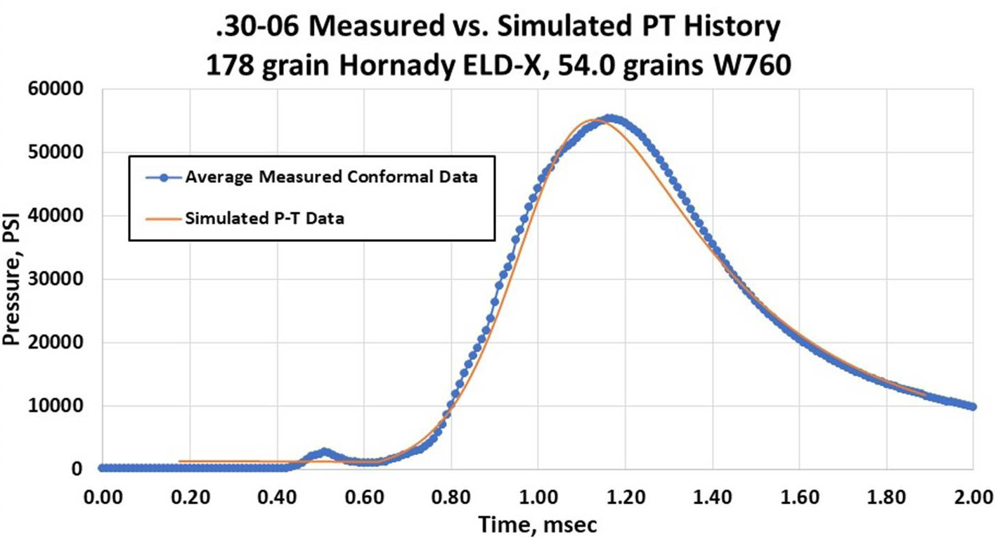
Figure 2. Comparison of Measured and Predicted Pressure-Time for the W760 Propellant (Source: Hornady Manufacturing Company/J. Siewert).
For purposes of balloting simulations, it is important to match peak pressure and muzzle velocity, as well as the pressure rise rate; those parameters influence the structural dynamic behavior of the bullet-barrel combination. Qualitatively, the propellant model for the W760 propellant is in good agreement with measured data, as shown in Figure 2. Similar characterizations were performed for the other propellants examined.
Figure 3 shows the predicted average pressure-time histories for the studied propellants and respective charge weights. Statistical variations were generated for each powder based on the measured muzzle velocity standard deviation during firing.
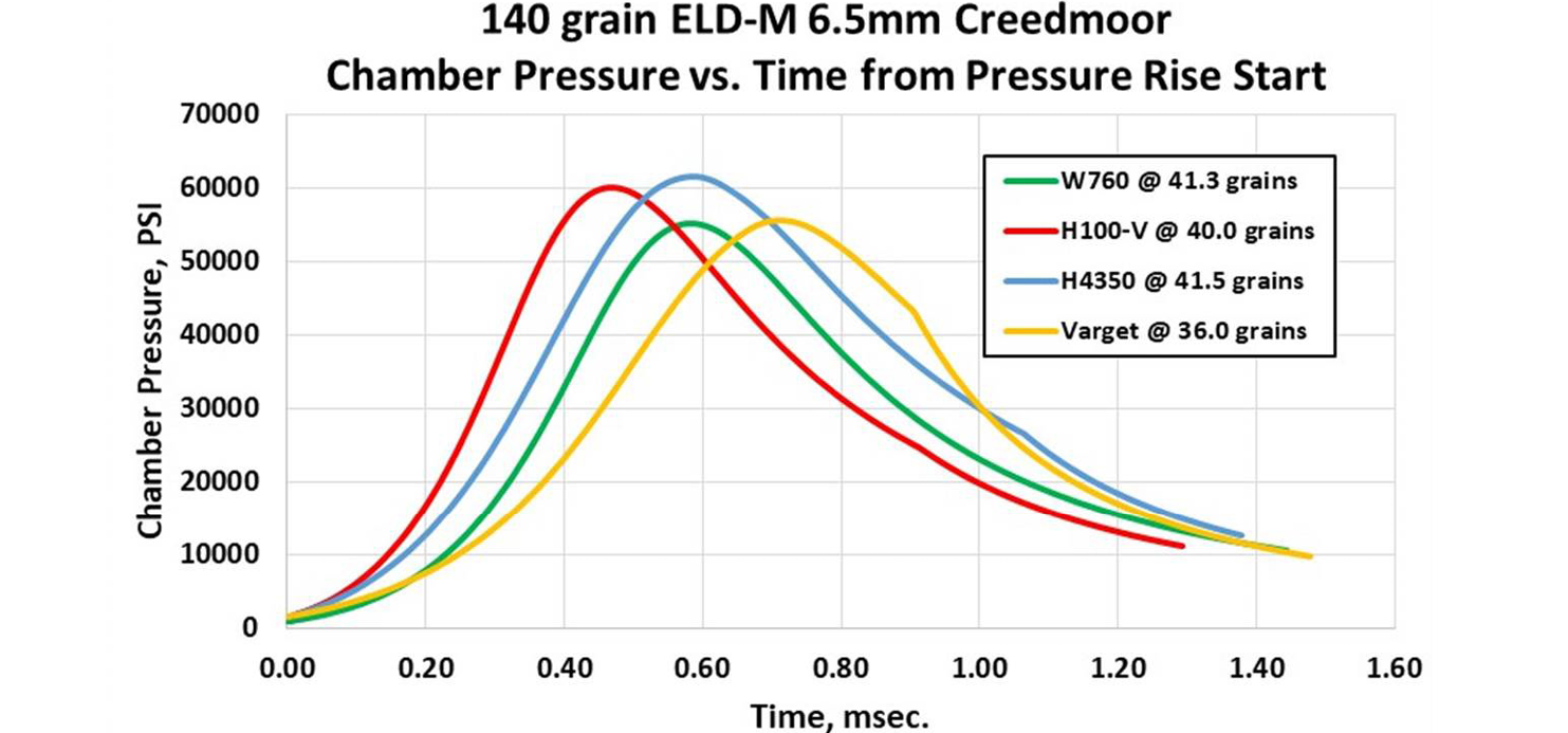
Figure 3. Comparison of Pressure-Time History for Studied Powders (Source: J. Siewert).
Interior ballistics profiles were generated representing the average performance, along with plus and minus 1, 2, and 3 standard deviations from the mean. Figure 4 shows the mean performance for the 6.5-mm, 140-gr ELD-M when fired with 41.5 gr of H4350 propellant, along with the plus and minus 1, 2, and 3 standard deviations in muzzle velocity from the mean using a single resistance pressure vs. in-bore travel profile for all powders and variations. Similar simulations were made for Varget, H100-V, and W760 to enable execution of balloting simulations with Monté Carlo draws for pressure-time forcing functions.
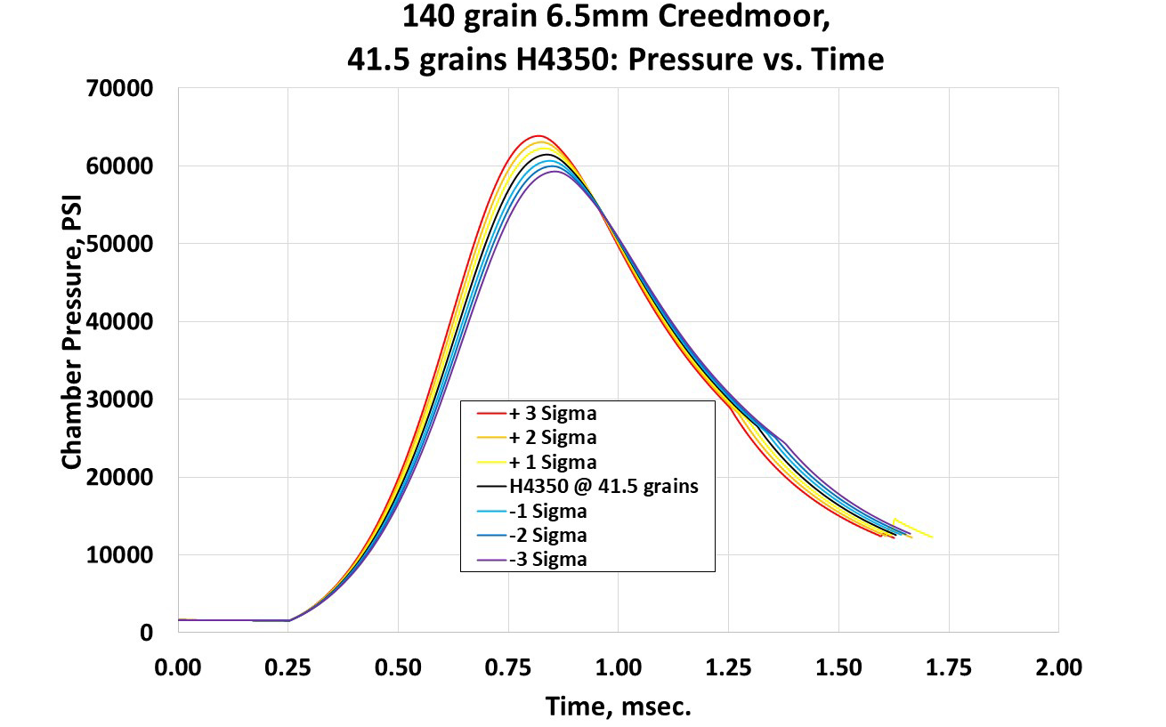
Figure 4. H350 Pressure vs. Time With Standard Deviations (Source: J. Siewert).
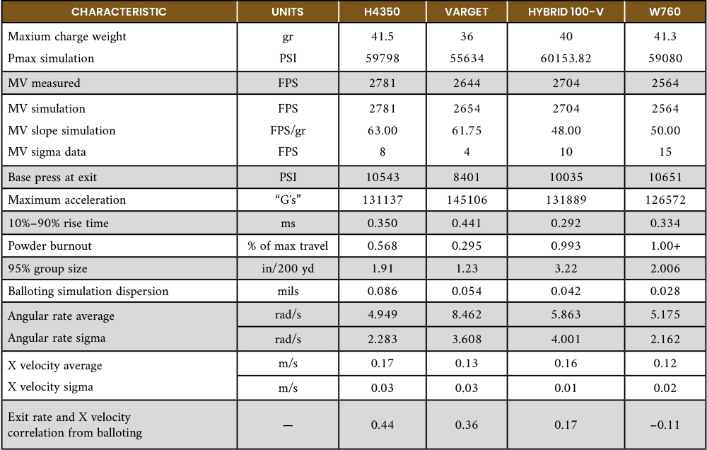
A summary of the propellant test characteristics used in this study is shown in Table 1.
Table 1. Summary of Propellant Test Performance (Source: J. Siewert)

Note: FPS = feet per second and PSI = pounds per square inch.
Projectile Balloting Models
The balloting simulation uses lumped mass and beam element models of the projectile and barrel to replicate the interaction of a flexible projectile in a flexible gun tube. In addition to the statistically variable pressure-time forcing functions, bore curvature and variable initial conditions of the projectiles are input.
Figure 5 shows a comparison between the physical model of the 6.5-mm projectiles studied (top half of the images), along with the lumped mass and beam element model used by the balloting code and springs that support the projectile in the barrel as it accelerates along the tube (bottom half of the images). The studied projectiles are the 6.5-mm, 140-gr ELD-M and the 6.5-mm, 130-gr copper alloy expanding (CX) bullet.
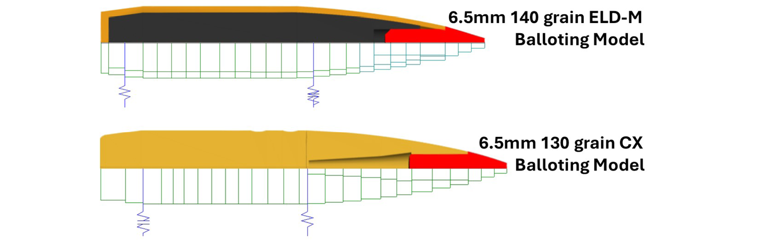
Figure 5. Comparison Between the 6.5-mm Bullets Physical and Balloting Models (Source: J. Siewert).
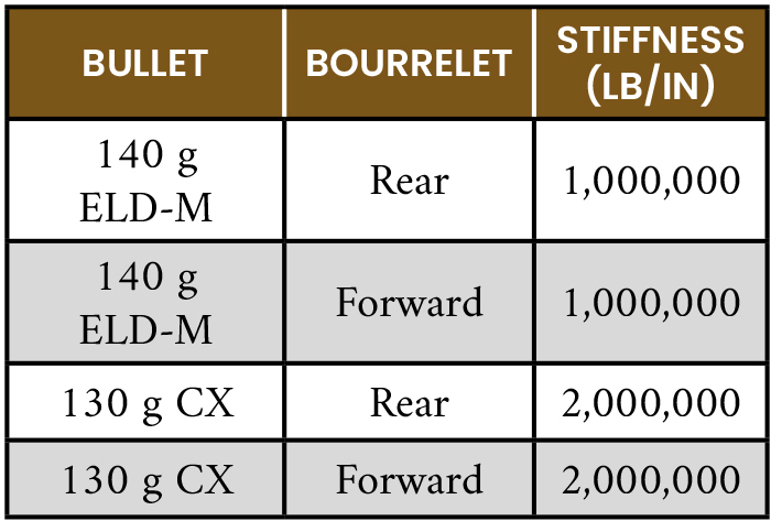
The support springs connecting the projectile to the internal bore surface of the barrel are key to determining the dynamic response of the bullet to the longitudinal and lateral accelerations imposed on the structures by the firing event. For this study, values determined by finite-element analysis for similar projectiles were used. Table 2 shows the spring support stiffness values used for this study for the ELD-M and CX bullets.
Table 2. Stiffness Values for the 6.5-mm Bullet Bourrelets (Source: J. Siewert)
Barrel Balloting Models
The balloting simulation also requires lumped mass and beam element models for the barrels being assessed. Figure 6 shows the 6.5-mm physical model (above the horizontal centerline) and the lumped mass and beam element model used by the balloting simulation for the “tapered barrel” assessments.
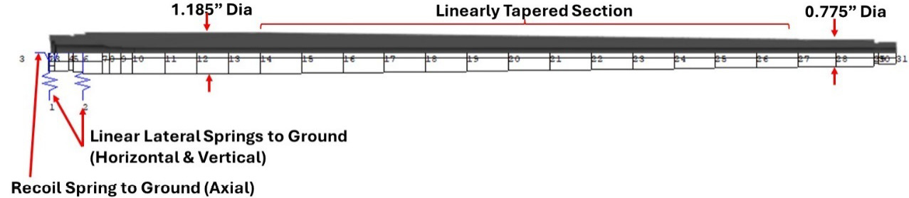
Figure 6. “Tapered” Barrel Physical and Balloting Models (Source: J. Siewert).
Figure 7 shows the 6.5-mm physical model (above the horizontal centerline) and the lumped mass and beam element model used by the balloting simulation for the “heavy barrel” assessments.
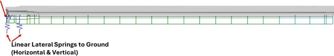
Figure 7. “Heavy” Barrel Physical and Balloting Models (Source: J. Siewert).
For several of these analyses, the support springs were moved from the aft (chamber) end of the barrel to a mid-barrel location to assess the effect of moving the barrel clamping location on the resulting projectile exit state’s (angular rate and cross velocity) distribution and concomitant dispersion. The “statistical” simulation runs 500 iterations performing a Monté Carlo draw on the projectile’s initial position and IB’s forcing function; but for these analyses, the simulations were run twice to obtain 1,000 replications per unique set of interface and boundary conditions.
Another important input to the balloting simulation is the bore centerline profile (bore straightness). Figure 8 shows the two vertical bore centerline profiles—“benign” and “moderate” bores. The bores are straight in the horizontal plane.
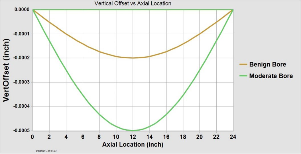
Figure 8. Bore Centerline Deviation vs. In-Bore Travel (Axial Location) (Source: J. Siewert).
Projectile Initial Conditions
The last important input set for the balloting simulations is the initial conditions for the projectile(s). The two primary input categories that determine the projectile’s initial position are the bourrelet diameter (mean and standard deviations) and the establishment of the projectile’s initial plane of motion. These inputs are shown in Figure 9 with the blue and red arrows, respectively.
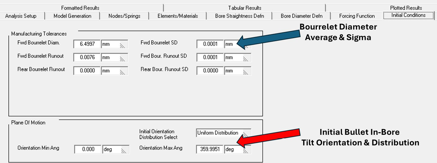
Figure 9. Initial Conditions Input for the 6.5-mm Bullet (Source: J. Siewert).
Two general sets of initial plane-of-orientation conditions were explored—the first being a limited set of pointing angles and the second being an unlimited set of pointing angles. For guns with a spring-loaded ejection plunger, the force applied to the base of the cartridge case by the plunger was thought to result in a preferred initial pointing orientation (“around-the-clock” as viewed from the breech) of the bullet as it was placed into the barrel.
The “uniform” distribution was subsequently determined to be preferred, as the limited set of pointing angles typically resulted in a “skewed” fall of shot distribution (horizontal vs. vertical axis larger or vice versa), which was inconsistent with typical observed circular dispersion patterns.
Simulation Results
Initial propellant-bullet-barrel simulations were made in the benign, tapered barrel. A plot was made of the bullet exit states, initial angular rate, and initial cross velocity magnitudes as a function of standard deviation from the mean for each propellant. This yielded some very interesting “exit state response maps” for the 140-gr, 6.5-mm projectile. Plots for each of the propellants are shown in Figure 10. The differences among all the propellants are interesting, and the impact point for an individual shot is the result of a paired set of exit state angular rate and cross velocity at a given distance from the mean for a particular randomly selected, IB forcing function.
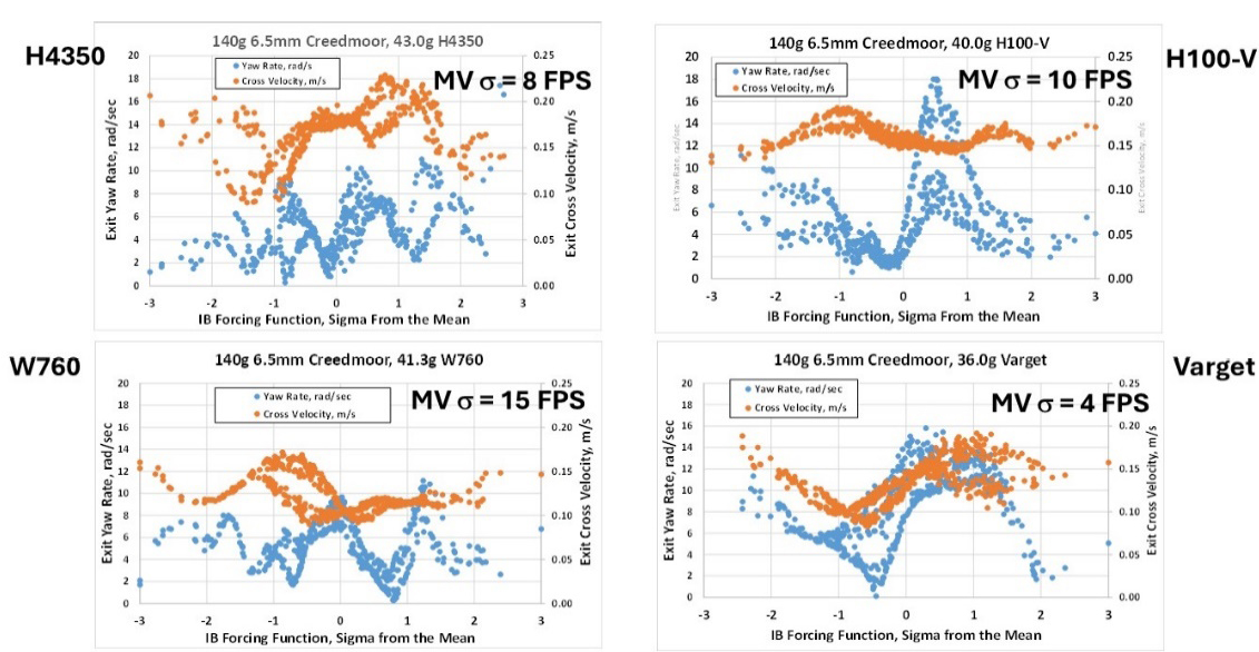
Figure 10. ELD-M Exit States vs. Propellant Type in a Benign, Tapered Barrel for the 140-gr, 6.5-mm Projectile (Source: J. Siewert).
As seen in Figure 10, all the initial yaw rate plots exhibit significant “waves” in their response to changes in pressure-time history; some zones of pressure-time performance are much more likely to result in larger initial yaw rates, and some velocity zones are far less likely to exhibit high exit rates. The same can be said for the cross-velocity behavior but to a much lesser extent.
Of particular interest in Figure 10 is the exit yaw rate response of the Hybrid H100-V, shown in the upper right corner between 0 and +1 standard deviation from the mean. Here, the structural response is “bifurcated,” with some shots exhibiting relatively large yaw rates and others exhibiting small yaw rates, with nearly nothing in between. For this propellant-bullet-barrel combination in the region between the mean and plus-one standard deviation above the mean, ~1/3 of shots exit with an angular rate above 10 rad/s, while 2/3 are below that figure, all while exhibiting a narrow band of cross-velocity response. This response anomaly was intriguing and studied further, as discussed next.
Based upon Bob McCoy’s “Modern Exterior Ballistics: The Launch and Flight Dynamics of Symmetric Projectiles” [2], the aerodynamic “jump” from the initial angular rate is in a direction that tends to cancel the “throw” arising from the bullet cross velocity at muzzle exit, provided the cross velocity is caused only by the center of gravity (CG) offset of a “perfectly made” bullet that is tipped in-bore relative to the bore centerline at muzzle exit. In this case, the exit angular rate and cross velocity should be well correlated, with a correlation coefficient of 0.75 or greater. An examination of the exit states captured from this analysis shows the correlation coefficient of all the propellants studied under any set of boundary conditions was no greater than 0.45. This means that the cross velocity of the propellant-bullet-barrel combinations studied most likely arises from the combined effects of barrel pointing and transverse motion and not the product of CG offset multiplied by the exit spin rate.
It should be noted that the velocity “period” of the structural dynamic response changes is on the order of one or two velocity standard deviations, meaning that the (re)loader does not have any chance to “tune” the muzzle velocity to a point where the large exit yaw rates do not occur. The effect of changing average muzzle velocity on the structural response for the Hybrid H100-V is shown in Figure 11, along with several other changes in the “system” parameters.
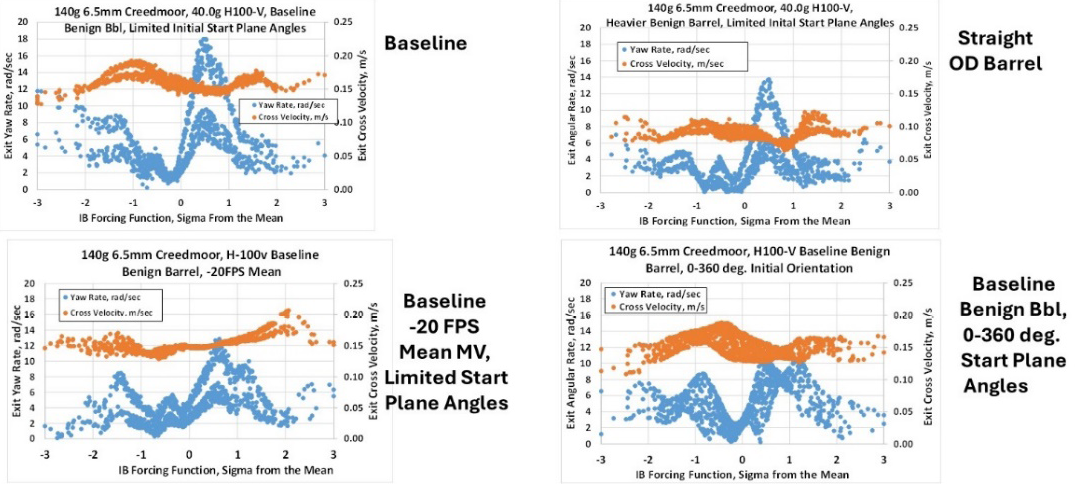
Figure 11. ELD-M Exit States vs. Various Interface Perturbations for the 140-gr, 6.5-mm Projectile (Source: J. Siewert).
Since the exit yaw rate structural response “map” of the Hybrid H100-V propellant was so interesting between the mean performance and plus-one standard deviation, bullet-barrel interface parameters that could be changed to modify the response in that region were explored. Figure 11 shows the “baseline” simulation response (tapered, benign barrel with limited initial projectile tilt plane angles shown in the upper left), along with the response with a barrel with a straight outside diameter in the upper right. Unsurprisingly, a reduction in both angular rate and cross velocity is seen since this change increases the bending stiffness of the barrel and its mass.
The structural response with the same benign, tapered barrel with limited start planes is seen in the lower left-hand corner of Figure 11. However, the average muzzle velocity has been reduced by 20 FPS, along with all the velocity standard deviations. This value was chosen because if the exit state structural response related solely to the average muzzle velocity, a 20 FPS shift in velocity should have moved the bifurcated response to the plus 2–3 sigma range if the behavior was linearly sensitive to muzzle velocity alone. Interestingly, while there is a reduction in angular rate between the mean and plus-one standard deviation, there is still a bifurcation in the yaw rate response in that region with the chosen set of initial conditions and the bore straightness profile.
Subsequently, the initial conditions were changed from limited start plane angles to unlimited, meaning the axis of the bullet can randomly point anywhere “around the clock” as viewed from the chamber when the cartridge is seated. With this set of initial conditions for the projectile, the angular rate “bifurcation” between the mean peak pressure and plus-one standard deviation essentially disappeared and was replaced by a broader, reduced angular rate response.
Next, the bullet exit state response was evaluated for the tapered, benign barrel, with the connection between the barrel and “ground” changed from the aft end of the barrel at the chamber to the middle of the barrel. The structural response maps for this analysis are shown in Figure 12. The supports at the aft end are shown on the left-hand side of the figure, while the response for the system with the barrel supports located at the mid-barrel location is shown on the right. There is a clear reduction in exit angular rate and cross velocity with the mid-barrel support location. This clearly supports the decision of the manufacturers to connect the barrels to their slide block assemblies’ mid-barrel as the “low dispersion” choice.
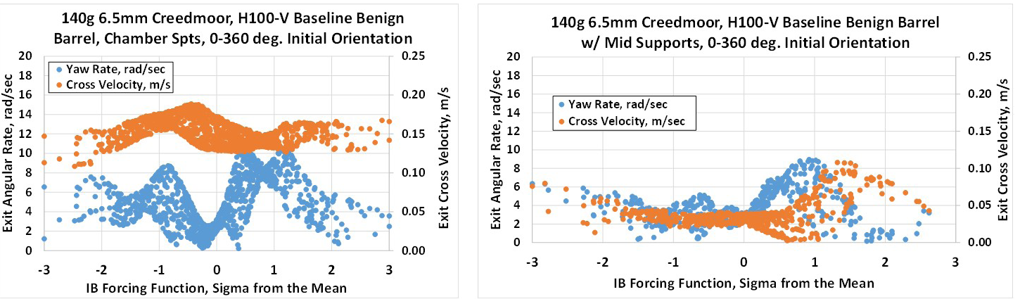
Figure 12. ELD-M Exit States vs. Barrel Support Location for the 140-gr, 6.5-mm Projectile (Source: J. Siewert).
From there, the exit state structural response caused by arbitrarily changing the support stiffness of the projectile was evaluated. This is an academic exercise in that the support stiffness of the bullet is determined primarily by the bullet construction and materials. While the bullet support stiffness can be reduced some using cannelures, the reduction in bourrelet stiffness to 750,000 lb/in is exceptionally small given the bullet construction.
Figure 13 shows the exit state response map for the 6.5-mm, 140-gr ELD-M projectile, with 1.5 million lb/in support stiffness on the left and 750,000 lb/in stiffness on the right. There is a clear reduction in both exit yaw rate and cross velocity, with reduced support stiffness. This result runs contrary to the general experience of medium- and large-caliber ammunition.

Figure 13. ELD-M Exit States vs. Bullet-Barrel Support Stiffness for the 140-gr, 6.5-mm Projectile (Source: J. Siewert).
Lastly, curiosity about the exit state response map and expected dispersion of the 140-gr, 6.5-mm ELD-M compared to the monolithic copper alloy 130-gr, 6.5-mm CX projectile for the two bore centerline profiles analyzed prompted comparative investigations about these two bullets. Figure 14 shows the exit state structural response maps of the ELD-M projectile on the left, with the CX projectile response on the right. The exit state response of the bullets to the barrel with a 0.0002-in maximum bore centerline deviation is on the top, while the maps for the same bullets and initial conditions with 0.0005-in maximum bore centerline deviation are on the bottom.
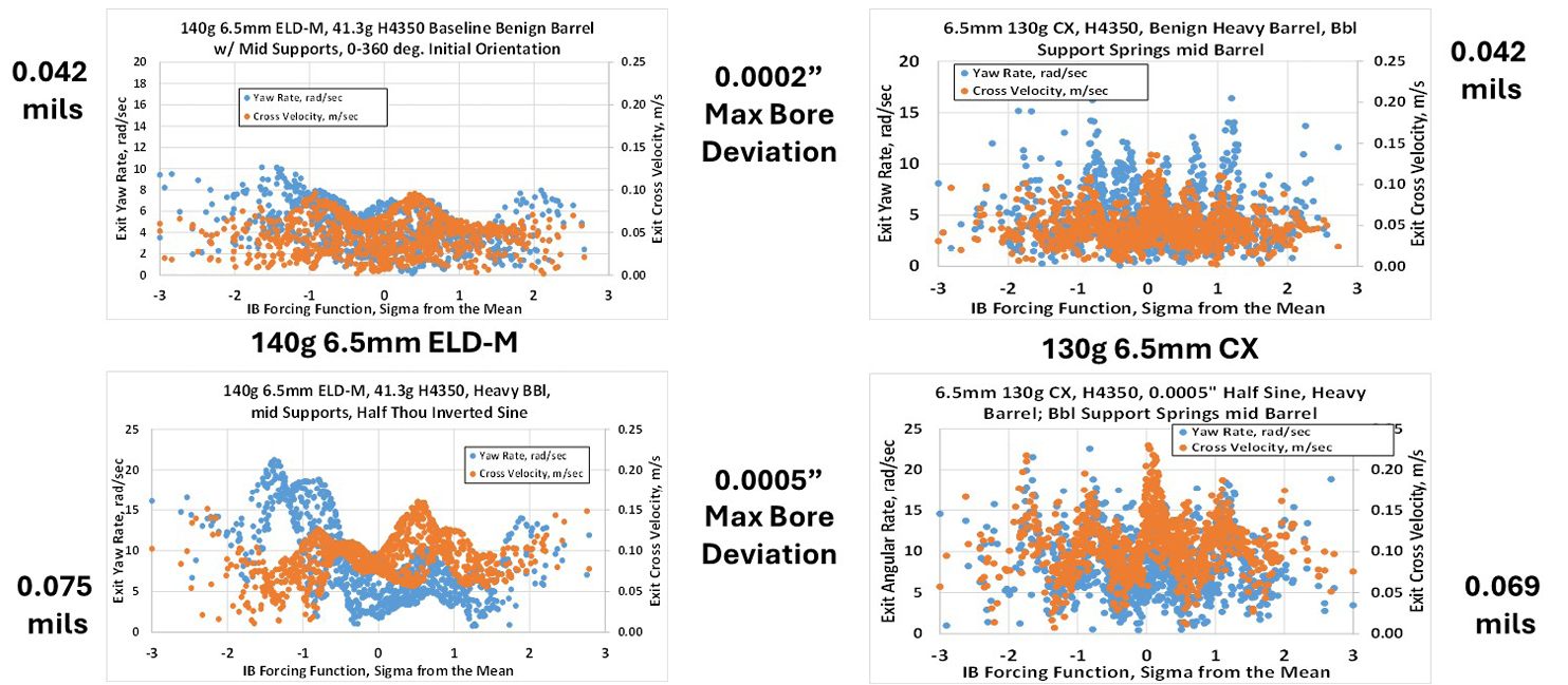
Figure 14. ELD-M and 130-gr CX Exit States vs. Max Bore Deviation for the 140-gr, 6.5-mm Projectile (Source: J. Siewert).
It is clear in Figure 14 that the exit yaw rate and cross velocity of the CX bullet are more sensitive to changes in pressure-time history than the ELD-M, but the dispersion performance appears to be comparable with an identical bore shape. Because these results are for the analyzed bore centerlines that are half-sine waves, the comparative dispersion performance of these bullets may be considerably different in barrels with different bore centerline shapes. The cleanliness of the barrel will play a significant role in the observed dispersion.
Table 3 lists the interior ballistics simulation and dispersion simulation performance of the 6.5-mm, 140-gr ELD-M projectile vs. the various propellants examined.
Table 3. ELD-M – Propellant Characteristic Performance Summary for the 140-gr, 6.5-mm Projectile (Source: J. Siewert)
As shown in the last row of Table 3, there is generally poor correlation between the bullet exit states and the interior ballistics performance. This means that the extremes in pressure-time performance are NOT responsible for the large angular rate and/or large cross velocity that cause the “fliers” that plague all shooters.
How do the results of the balloting simulation compare to the dispersion seen during testing? Figure 15 shows the dispersion seen in product testing vs. propellant type and the dispersion predicted by the balloting code.
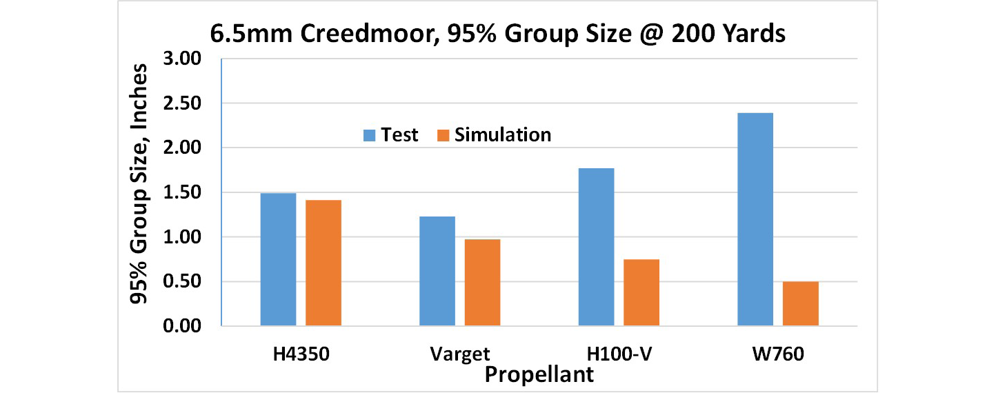
Figure 15. ELD-M Measured vs. Simulated Dispersion for the 140-gr, 6.5-mm Projectile (Source: Hornady Manufacturing Company/J. Siewert).
As seen in the figure, the dispersion predicted by the balloting code of the 6.5-mm, 140-gr ELD-M using the two extruded powders, H4350 and Varget, is in close agreement with the dispersion observed in test, while the H100-V and W760 results do not agree well at all. Years of experience with the balloting code has shown if the predicted dispersion is radically different from that observed in test, the most likely cause is something the balloting code does not consider, like a disturbance from reverse flow at muzzle exit. The H100-V and W760 are hybrid and ball powders, respectively, and the interior ballistic simulations indicate these powders may not be completely consumed at muzzle exit. Unburned propellant grains striking the aft end of the projectile at shot exit (along with accompanying high base pressures at exit) are the most likely explanation for this discrepancy.
Externally applied loads can cause significant additional dispersion if the load is applied in the “wrong” place. From previous studies on the dispersion of spin-stabilized bullets, if a fixed impulse is applied perpendicular to the longitudinal axis of a projectile for one-half revolution, the angle of attack and trajectory “jump” angle that result are shown in Figure 16. The minimum angle of attack developed by the projectile is seen when applied impulse is located at the projectile’s center of mass, while the minimum trajectory deviation (the “jump angle”) is minimized when applied perpendicular to the projectile’s normal force center of pressure location. Also shown is that the trajectory deviation is maximized when the impulse is applied at the aft end of the projectile, farthest from the normal force center of pressure.

Figure 16. Projectile Max Angle of Attack and Flight Path Deviation as a Function of Perpendicularly Externally Applied Impulse Location Along the Projectile Body (Source: J. Siewert).
If the base pressure at muzzle exit is excessively high and randomly asymmetric or unburned propellant grains strike the projectile at the bullet base, the dispersion of the projectile can be adversely affected.
Conclusions
Each combination of propellant, bullet, and barrel (geometry, support stiffness and location, twist rate, etc.) exhibits a unique “exit state structural response” due to the system structural response to the differing rise rates of the propellants used. These results conclusively show that propellant selection can indeed affect dispersion. Choosing a powder that burns out prior to muzzle exit will likely help keep groups small.
In viewing the various response maps, it is easy to see how a reloader could think a dispersion “node” had been found when shooting 3, 5, or 10 shot sample sizes. Propellant screening testing should thus be viewed as a “go/no-go” exercise for bullet-powder compatibility.
Acknowledgments
The author would like to thank the following companies:
- Arrow Tech Associates, Inc. [3] for the continued use of their analytical software.
- Hornady Manufacturing Company for their gracious sharing of test data.
References
- Outdoor Sportsman Group. Hodgdon Reloading Manual. New York, NY, 2021.
- McCoy, R. L. “Modern Exterior Ballistics: The Launch and Flight Dynamics of Symmetric Projectiles.” Atglen, PA: Schiffer Publishing, Ltd., 1 January 2004.
- Arrow Tech Associates, Inc. PRODAS software, www.prodas.com, 1998–2023.
Biography
Jeff Siewert is a retired ballistics engineer who has conducted studies on bullets, propellants, cartridge cases, trajectory matches, radar data reduction, bullet-barrel interactions (in-bore balloting and body engraving simulations), and rifling design in calibers ranging from 17 cal to 203 mm. His studies on small-caliber projectiles have included dispersion reduction on the M855A1 and M856A1; balloting and dispersion analyses for the next generation squad weapon, general purpose projectile; engraving force measurements on military and commercial bullets and studies on barrel configuration and dispersion; and case-chamber interaction studies to troubleshoot case failures. He is the 2024 recipient of the National Defense Industrial Association’s Chinn Award. Mr. Siewert holds a B.A. in physics from State University of New York at Oswego.