Introduction
Polyetheretherketone (PEEK) is a semicrystalline thermoplastic that was invented in November 1978 and brought to market in 1981 by Imperial Chemical Industries, which later became Victrex. As developed, this material possessed a maximum 48% degree of crystallinity. The composite material was introduced a year later as APC-1 with a 52% fiber volume, and it was optimized to yield APC-2 with a 63% fiber volume. The fiber adhesion properties of APC-2 resulted in superior impact and crack resistance compared to APC-1, as well as existing epoxy-based composites. The birth of the fiber-reinforced PEEK composite coincided with the push for composites on various aircraft applications to enhance performance while reducing weight. Properties associated with this material were very alluring to structures designers due to enhanced mechanical properties over epoxy fiber-reinforced composites and many metals. Improvements to these properties include the following:
- Extreme toughness/damage tolerance/survivability
- 150% ballistic damage tolerance improvement over aluminum
- >100% better impact resistance over toughened epoxy
- Enhanced energy absorption
- Improved damping
- Superior environmental/chemical/solvent resistance
- Excellent fatigue resistance
- Low water absorption
- No refrigeration/out-time/exotherm considerations
- Recyclable
- Melt processable (no cure chemistry, long soak times)
- No toxicity/hazardous chemical issues
- Excellent wear resistance
- Low friction coefficient
- Stable glass transition temperature—even under hot/wet conditions
- Hydrolytic stability (polymer dependent)
Despite the identified advantages associated with fiber-reinforced PEEK composites, designers have been slow to accept the material for several issues, including the following:
- Lack of robust material properties and/or design/allowables to support designing structures and support quality control activities in a production environment.
- Material fiber variability impact on mechanical properties and design.
- Lack of processing options that support translation of developed designs into structural realities.
- Ill-perceived elevated material and process costs (related to elevated processing temperatures and pressures) and limited material usage (globally) that directly impacts material costs and availability.
Since their inception, research and development activities have quickly resolved these concerns; however, the focus of designers has largely remained on epoxy-based, fiber-reinforced composites. This is largely due to their familiarity with the systems and the large investment in equipment, such as autoclaves and large freezers. Using proper design philosophy, one system does not take precedence over the other, but the one that is best suited for the application should be selected. To design primary structures with fiber-reinforced PEEK thermoplastic composite, a basic understanding of the issues that have plagued full acceptance of the material is required.
Material Properties
Since the development of the material, sufficient data have been collected to support the development of B-basis allowables based on the directions provided in the Composites Materials Handbook-17 (CMH-17). B-basis design allowables (90% probability with 95% confidence) can and have been recreated from data used in previous Army experimental programs. Once allowables are established, they are continuously updated as new data become available. The development of these allowables is possible by pooling data of different graphite fiber systems per CMH-17 guidelines. A large database of material information is required for establishing design allowables where the key is repetition of results. Typically, each resin and fiber combination requires a new set of design allowables. For small data populations, the result of any basis value calculation strongly depends on the sample size. Smaller sample populations are less costly to test, but this approach is limited because as the population size decreases, so does the calculated B-basis value. Not only does the estimated B-basis value increase with larger sample sizes, but as the one sigma limits illustrate, the expected variation in estimated value significantly decreases.
With data pooling, the IM7 fiber is superior to the AS4 and IM6 fibers in which it is grouped. Two possible effects from adding AS4 or IM6 data to IM7 data are described in Table 1.
Table 1. Effects on B-basis From Grouping Data (Source: R. Luzetsky)

Sample design allowables for the IM7/PEEK thermoplastic are illustrated in Table 2. These allowables have since been updated. However, due to their conservatism, they are still viable for developmental activities considering additional data may be necessary to address identified material or application data gaps.
Table 2. Sample Design Allowables for IM7/PEEK (Source: SURVICE Engineering)
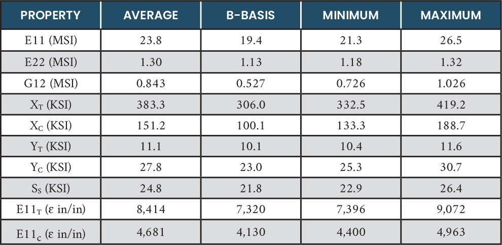
Since design allowable development can be a costly proposition, teaming with a company that has vetted design allowables provides a way to move forward with a prototype design so a particular application can be evaluated without the expenditure necessary to collect and develop a separate set of design allowables.
Once material design properties are established, composite lamination theory and finite-element modeling can be used to develop a design for a given application. The focus is to develop properties that meet and/or exceed the requirements for the component being developed. This is accomplished in conjunction with the capability provided by the fabrication process. Fortunately, for fiber-reinforced PEEK thermoplastic materials, a myriad of processes has been developed to provide configuration versatility for the designer.
Material Fiber Variability
Numerous fibers are compatible with the PEEK resin system, creating great design versatility. In addition to traditional graphite and glass fibers (E and S2), nickel-coated carbon fibers have been demonstrated. Recently, a multifunctional form of IM7/PEEK composite has been developed that exhibits structural properties and high levels of electromagnetic (EM) shielding. This material form involves integrating expanded copper mesh within the laminate construct and has exhibited the potential to create EM shielding levels exceeding 100 dB. Any time a new fiber type is introduced to the PEEK matrix, a series of tests, including shear, is implemented to determine any impact to the design allowables. With both the nickel-coated carbon and expanded copper mesh, deleterious effects were found to be minimal. When properly integrated, they can yield EM properties for the entire composite laminate greater than that of the base composite material (IM7/PEEK). The ability to select various fiber forms supports the ability to tailor material properties to a specific structural application.
Fabrication Processes and Techniques
Proper design with IM7/PEEK needs to consider the fabrication process. For IM7/PEEK, the available processes include autoclave, press or compression forming, double-diaphragm forming, in-situ tape placement, continuous compression molding (CCM), three-dimensional (3-D) printing with fiber-reinforced PEEK thermoplastic, and overmolding.
Autoclave
Autoclave processing requires using special high-temperature materials (vacuum bagging and sealing tape). A laminate stack is created by using a soldering iron to tack individual plies to one another. The laminate stack is aligned over a tool, and once the appropriate forming temperature is achieved, vacuum and pressure are applied to cause the laminate stack to form over the tool. Limitations exist in the potential shapes, as complex curvatures would be subject to an uncontrolled fiber wash, which would directly impact structural response characteristics.
Press or Compression Forming
Like autoclave processing, a laminate stack is created using a soldering iron to tack the individual plies to one another to form the stack. The laminate stack is placed over a tool in a high-temperature, pressure-platen press. The laminate stack is heated to the appropriate temperature, and the press is used to force the laminate stack either into or over the tool, as illustrated in Figure 1. There are some curvature and size limitations due to fiber wash during the application of pressure. With this process and the additive nature of the material, it is possible to form subelements and combine them into a larger unified structure with the press operations, as illustrated in Figure 2.
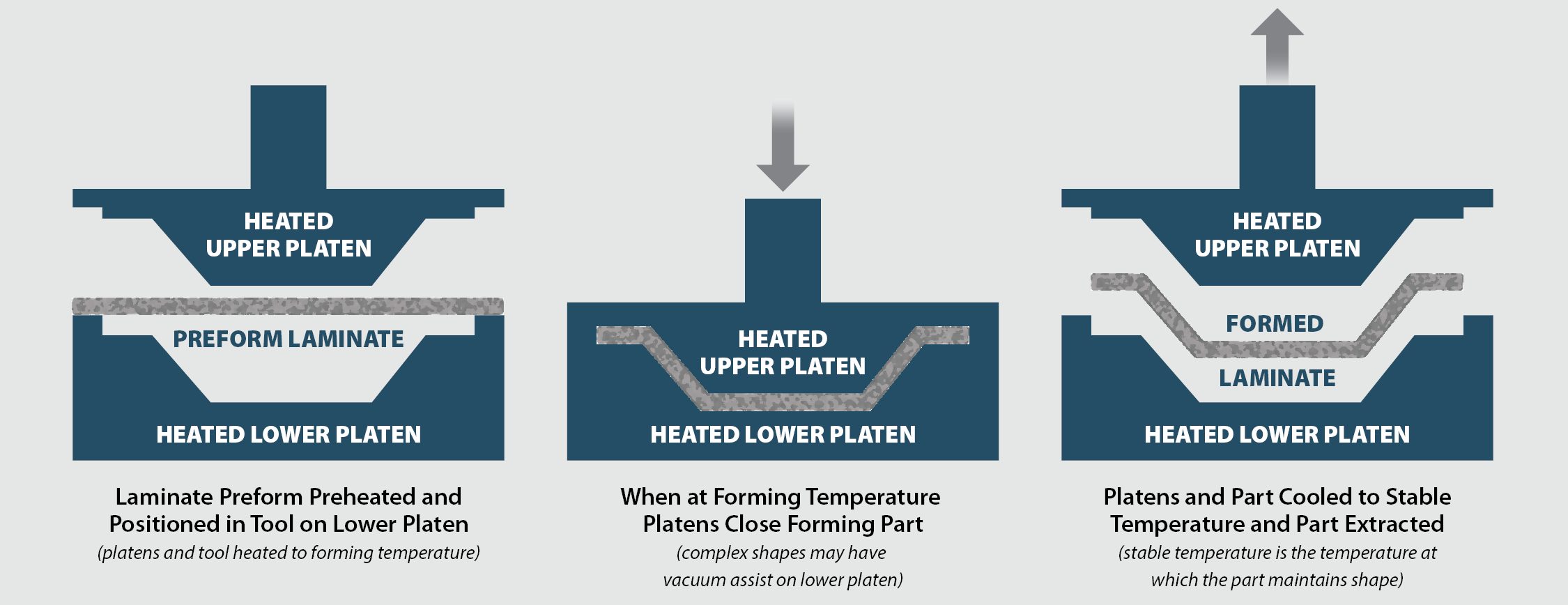
Figure 1. Press or Compression Molding Process (Source: H. R. Luzetsky).
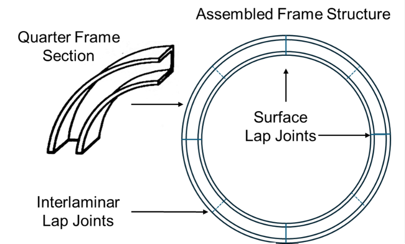
Figure 2. Segmented Frame Press Consolidated From Sections (Source: H. R. Luzetsky).
Double-Diaphragm Forming
Double-diaphragm forming is used for forming structures with integrated reinforcements, such as integrated reinforcing beads (Figure 3).
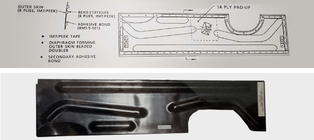
Figure 3. Prototype Landing Gear Door Formed From Double-Diaphragm Forming Process (Source: H. R. Luzetsky).
In this forming process, the laminate stack is placed between two sheets of superplastic aluminum suspended over a tool in a pressure vessel, as illustrated in Figure 4. The sandwiched structure is heated to the appropriate forming temperature. Once the temperature is reached, the tool is raised to contact the laminate structure and pressure is applied to form the material blank over the tool, followed by cooling. The aluminum forming sheets are required, serving as rigid caul plates for the operation while conforming to the underlying tool. These sheets are removed, revealing the formed composite structure. Due to the expense of the expendable materials, this is a process reserved for closed 3-D-reinforcing structures like that in Figure 3; it can be accomplished in a separate tool that does not require an autoclave for the vacuum and pressurization.
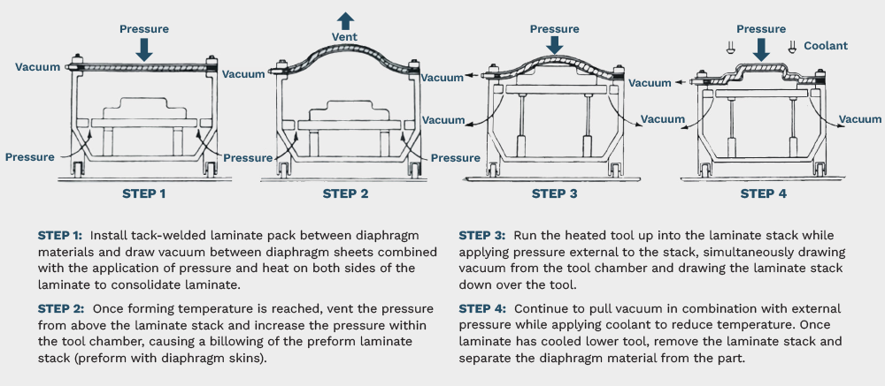
Figure 4. Diaphragm-Forming Process Using Superplastic Aluminum as Forming Sheets (Source: H. R. Luzetsky).
In-situ Tape Placement
With in-situ tape placement, an additive manufacturing process, localized application of heat and pressure with a compaction roller (as illustrated in Figure 5) mitigates processing with an autoclave or oven. It is considered an “on-the-fly” process in which the part is fully consolidated as the raw material is being put into place. The raw material is first heated using a heat source (hot gas torch stream or laser), and then it is consolidated/compacted with a rigid steel roller. There are no intermediate debulking steps or postprocessing needed. This process precludes the need for an external heat or pressure source to consolidate the composite laminate and is not limited by size restrictions. Since consolidation occurs with a compaction roller, the potential for fiber wrinkling is mitigated. With the in-situ tape placement additive manufacturing process, localized application of heat and pressure with a compaction roller allows for versatile fiber orientations supporting discrete fiber placement tailoring and optimizing structural properties.

Figure 5. In-situ Automated Fiber Placement (AFP) Process With Laser Heat Source (Source: TSS/Albany).
The laser heating source is a recent modification to the process that provides faster processing, improved efficiency, more control, and real-time temperature logging. The process affects a smaller heat-affected zone, thus reducing the chance of damaging a part by limiting the number of times it is heated and cooled.
This process also supports unlimited geometric considerations regarding structure size and wall thicknesses since it mitigates exotherm concerns typical for processing thick epoxy composites. Continuous, unidirectional, graphite fiber-reinforced PEEK thermoplastic is ideally suited for the in-situ fiber placement process (Figure 6). The raw material is delivered as a prepreg tape, meaning that the raw fibers are preimpregnated with the thermoplastic resin. This is done offline at the material supplier’s facility. Because the material is a thermoplastic, there is no shelf life and no “out-time” issues (i.e., the raw material can be stored at room temperature for an indefinite amount of time). This is different from thermoset materials, which require relatively strict storage temperatures and have a limited shelf life.
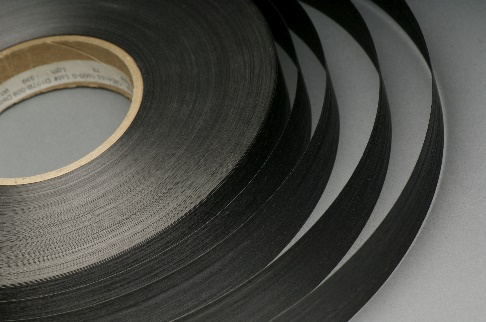
Figure 6. IM7/PEEK Thermoplastic Tape (Source: TSS/Albany).
In addition to process advancements, improvements in the raw tape material have resulted in reduced voids in the prepreg tape. This translates to a lower void content in the finished product. The material in tape form has a void content <1%, which is carried through to the final part configuration.
Due to the additive nature of the in-situ tape placement process, it is used for no-fastener assembly. This process involves: (1) fabricating individual reinforcements, (2) creating a segmented breakaway tool, (3) loading the tool with the reinforcing structures that are flush with the tooling outer surface, and (4) overwinding the entire structure fusing the reinforcing structures to the skin and yielding a coconsolidated structural assembly with no fasteners. Removal of the breakaway tooling releases the assembled structure to the next operation. A typical breakaway tool is shown in Figure 7, and the resulting coconsolidated structure with no fasteners is shown in Figure 8.
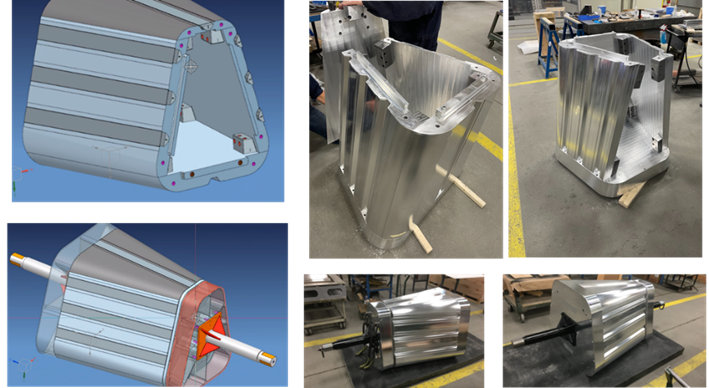
Figure 7. Breakaway Tool for Reinforced Fuselage Structure (Source: H. R. Luzetsky).
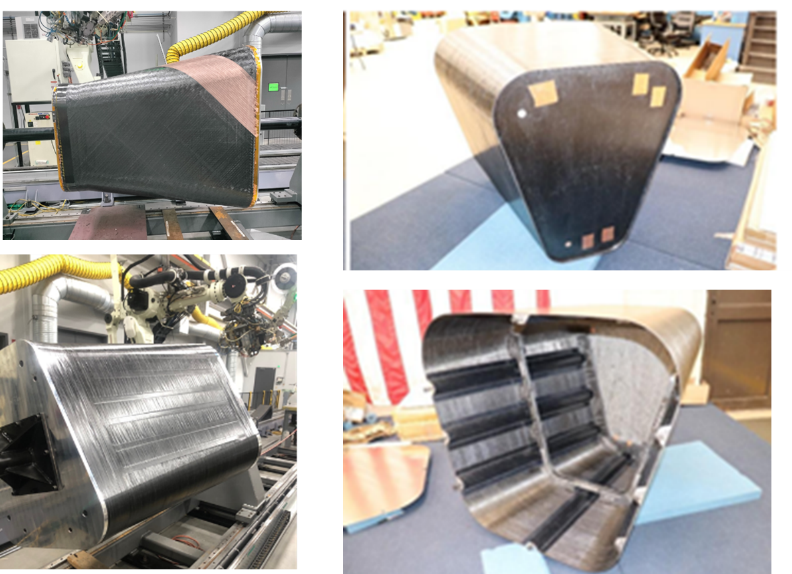
Figure 8. No-Fastener Assembly Structure (Source: H. R. Luzetsky).
Using this process with a proprietary tape placement head, expanded copper mesh has been discretely placed within the laminate. This has resulted in a multifunctional composite form that provides both structural and EM shielding properties. A prototype unmanned aerial system (UAS) fuselage shown in Figure 9 exhibits EM shielding effectiveness between 60 and 110 dB, depending on frequency. The multifunctional material was developed by integrating expanded copper mesh into an IM7/PEEK laminate through the in-situ tape placement process. Its orientation within the laminate is critical to developing the mechanical and EM shielding properties as well as contributing to the overall physical properties (e.g., environmental resistance, damage tolerance, and durability).

Figure 9. Multifunctional UAS Structure With Integrated EM Shielding and Lightning Protection (Source: H. R. Luzetsky).
CCM
The basic CCM process (illustrated in Figure 10) begins with the feed creel, which is loaded with as many rolls of semifinished thermoplastic composite input material as required to form the specified laminate. Angled plies not readily spooled are cut and butt-welded edge to edge or tacked together to form a multilayer panel of a specified stacking sequence. This welded laminate is then loaded onto the feed creel. A hydraulic feed mechanism pulls the input material into stainless steel “preformers” prior to entry into a shaped die. The partially formed material is brought to flow temperature and pulled into a compression molding press with steel dies for the desired shape profile. The continuous consolidated shaped profile exits the press area and is automatically cut and stacked.

Figure 10. CCM Process Flow (Source: TSS/Albany).
3-D Printing With Fiber-Reinforced PEEK Thermoplastic
The application of carbon/PEEK 3-D printing was explored for developing complex curvature structural sections to reduce cost and take advantage of integral reinforcement not possible with standard composite fabrication techniques. A Desktop Metal FiberTM 3-D printer was used for this program (Figure 11). This technology features two printheads—one for 3-D printing chopped, fiber-reinforced filament and another for laying down continuous fiber prepreg tape. While the continuous fiber tape process, dubbed micro automated fiber placement, permits fabrication of parts with up to 60% fiber volume fraction, the technology is limited to flat/nearly flat geometries. On the other hand, the chopped fiber filament process, which offers up to 30% fiber volume fraction and improved mechanical properties compared to standard thermoplastics, is nearly unlimited when it comes to geometry.
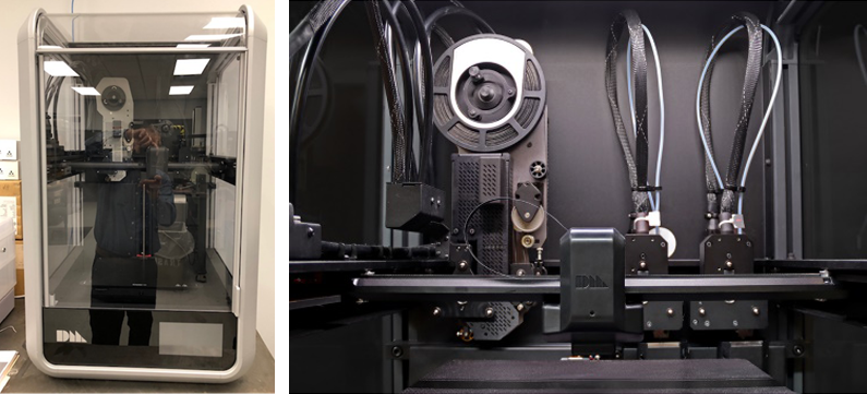
Figure 11. Desktop Metal 3-D Printer (Source: TSS/Albany and Desktop Metal Proto3000 Fibre Brochure).
With 3-D printing, a complexity is developed in a structure that is not possible with other processing techniques. The complexity of the structure compensates for property reduction associated with the 3-D process using chopped carbon fibers. However, there are advancements in the process that use continuous fibers to raise the mechanical properties compared to those associated with other processes (i.e., in-situ tape placement, press, and autoclave). This is illustrated with a frame that was developed with this process, shown in Figure 12. The frame was constructed of rib-reinforced sections like those shown in Figure 12 using the 3-D printing process. Each frame section had a connection joint included in the 3-D print. Each section aligns with one another, with their positions located/secured with a butterfly joint and joined with a splice plate on either side (see Figure 13). The butterfly joint and splice plates are secured to the frame sections with an epoxy adhesive. These joints are flush with the frame web area, and the plates are placed on either side of the web area, effectively tripling the thickness. In addition, the splice plates are ~3 inches long to completely cover the butterfly joint. The frame consists of 10 sections joined to one another with butterfly joints and splice plates, as shown in Figure 14.

Figure 12. With 3-D printing, a complexity is developed in a structure that is not possible with other processing techniques (Source: H. R. Luzetsky).
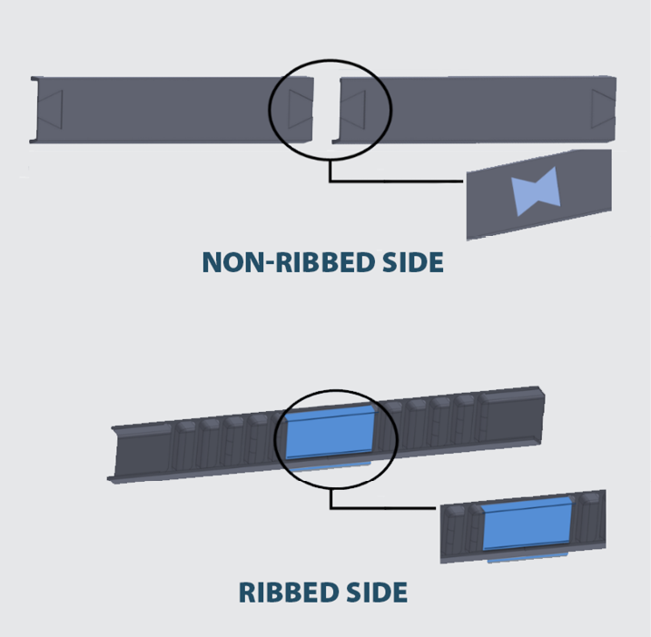
Figure 13. Frame Section Assembly Connections (Source: H. R. Luzetsky).
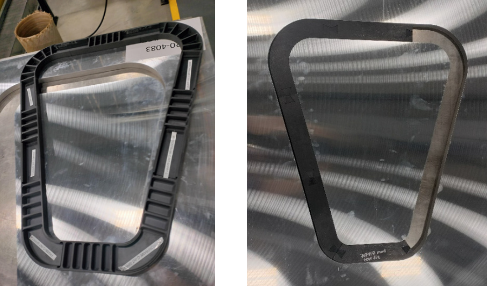
Figure 14. Assembled Frame Showing Ribbed Side (Left) and Reversed Side (Right) (Source: H. R. Luzetsky).
Overmolding
Overmolding is a process by which a part is created with two or more materials combined into a single unit or component. An example is illustrated in Figure 15, where a fastener insert is molded into the component needing a point of connection such as that required for an access door or some other type of structure that normally would be secondarily attached to the composite structure. This process eliminates secondary operations that can drive costs from an installation and maintenance perspective.

Figure 15. Examples of Overmolded Components (Source: CW CompositesWorld [1] and IQS Directory [2]).
Material and Process Costs
A carryover from the initial development is a continuing misconception that the use of fiber-reinforced PEEK costs more than an epoxy composite. This may seem to be true on the surface; however, accurate cost accounting must include life-cycle costs and consider costs associated with the volume of material used throughout global industry. When these elements are considered, the costs are comparable to an epoxy composite and may be significantly less. The lower costs are driven by the superior mechanical properties, which support a thinner structure and therefore less weight and material. With the reduction in weight comes enhanced performance and lower fuel costs. In addition, improved damage tolerance reduces maintenance costs, which directly impact life-cycle costs. Finally, making full use of the material and its fabrication processes supports a no-fastener assembly through applying coconsolidation to fuse individual components to a base substrate. This process eliminates assembly costs, which contribute significantly to lower system costs. Finally, studies have shown that as the quantity of material used increases industry-wide, the raw material costs decrease to a level comparable to that associated with epoxy-based composite materials.
Conclusions
PEEK thermoplastic composite is suitable for applying to a primary structure. With proper design and fabrication techniques, the resulting structures can exhibit the following characteristics:
- Enhanced performance, including damage tolerance and mechanical properties.
- Reduction in weight for the same performance levels attributed to the reduction or elimination of fasteners simplifying assembly.
- Thinner gage materials required due to the improved mechanical and damage tolerance properties.
- Lower life-cycle costs, which account for enhanced performance and reduced maintenance requirements due to improved damage tolerance and environmental resistance.
- Reduction in structural fabrication costs associated with elimination of fasteners, out-of-autoclave processing, and reduction in parts’ count.
One size does not fit all, and the fabrication process must be an integral part of the design process to optimize structural properties while minimizing costs and weight.
References
- CW CompositesWorld. “Overmolded Accessed on 15 June 2024.
- IQS Directory. “Plastic .
Biography
Harry “Rick” Luzetsky is a subject matter expert at the SURVICE Engineering Company, with more than 40 years of experience in composites and more than 30 years of experience in survivability. With a specific expertise in design, test, and research and development, he has helped develop and assess survivability features for numerous aircraft and has been active in composite design for vehicle performance and survivability improvements. He is the lead engineer for SURVICE’s role in developing the thermoplastic drive shaft and a coauthor of a pending patent on an advanced fuel containment technology and fiber-reinforced structural composite faraday cage enclosure for electronics. Mr. Luzetsky holds a B.S. in materials engineering from Drexel University.


