BACKGROUND
The military has shown an increased interest in developing lightweight technology solutions for current and future platforms. A large portion of this work is related to materials. New alloys are constantly being created that show benefits from two main perspectives. The first is evaluating materials that perform equivalent to the current solution at a lighter weight, and the second is materials that show an increase in performance at the same weight. A large amount of characterization must be performed to process, integrate, and evaluate in order to establish design criteria for use in military applications.
There is large interest in the U.S. Department of Defense (DoD) industry for using aluminum alloys for survivability-related applications because it has a low density when compared to current solutions and is relatively inexpensive when compared to other lightweight armor materials such as titanium. One aluminum alloy has shown a significant benefit in armor applications—2139-T8 aluminum alloy. This alloy is particularly interesting due to its ability to maintain material properties for all thicknesses. This is a significant improvement over other 2XXX and 7XXX series of high-strength aluminums.
There is a significant amount of data currently available that show 2139-T8’s benefit regarding survivability applications; however, there is recent interest in its use for vehicle hull structures. This increases complexity in manufacturability and sustainment. The alloy can be gas metal arc welded (GMAW); however, the strength and elongation of the welds are 35%–55% of the base material. As an alternative, friction stir welding (FSW) can be used. FSW is a solid-state welding process that uses a nonconsumable rotating tool coupled to a high-torque motor which moves along the joint of two plates, resulting in a butt weld. It is not a new technology; traditionally, the military has not utilized it during the hull manufacturing, mostly due to material selection. With the increase in emphasis for better performing technologies at lower weights comes a need to use these alloys in hull structure technologies.
There is a significant amount of data currently available that show 2139-T8’s benefit regarding survivability applications.
Figure 1 shows a basic description of FSW. FSW has four different zones used to describe material condition. They are unaffected material, heat-affected zone (HAZ), thermomechanically-affected zone (TMAZ), and weld nugget, which is part of the TMAZ. The TMAZ and weld nugget are different when compared to GMAW. FSW also has a significantly smaller HAZ when compared to GMAW due to the reduction in heat input into the joint during welding. From a material preparation standpoint, there are many benefits to FSW because, in most cases, the joints can be welded with very little modification. Beveling the edges of the joint to ensure full penetration is not required; therefore, cost is reduced. Additionally, the joint tolerances tend to be significantly improved and consistent using this process.
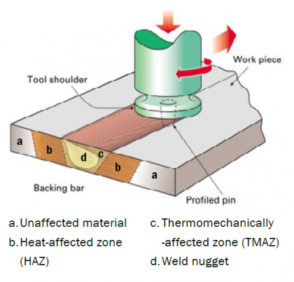
Figure 1: Description of FSW (Source: TWI Ltd.).
There are many benefits to FSW because, in most cases, the joints can be welded with very little modification.
Quasistatically, FSW has maintained 75%–85% of the base material properties in tensile strength and increased the elongation of the material in the joint by 15%–20%.
Although the material characteristics of FSW 2139-T8 aluminum are understood, additional investigation is needed for material fatigue. This is because military vehicles perform in very rigorous environments and use conditions, and the hull structure is exposed to many different loads and cycles during its life.
GOAL
The goal for this effort was to develop stress-life (S-N) curves for both base material and friction stir welded states. This would provide basic information on the rolled armor aluminum plate as well as increase or decrease performance after undergoing the solid-state welding process.
CHALLENGES
Due to the residual stress in the base plate and in the friction stir welded samples, the specimens were very difficult to machine in tolerance. Additionally, when working with aluminum, polishing the specimens to remove surface impurities that affect testing required special considerations over steel samples.
IMPACT
Fatigue data is required when developing new platforms. This data not only shows the capability of the 2139 aluminum alloy but shows the potential benefits of FSW and its use in hull manufacturing. This provides the Army with the data required to implement new lightweight materials to modernize its current and future fleets (as demonstrated by the prototype hull shown in Figure 2).
![Figure 2: Friction Stir Welded Hull Prototype Designed by the Ground Vehicle Systems Center and Fabricated by Concurrent Technologies Corporation (Source: U.S. Army Combat Capabilities Development Command [CCDC] Ground Vehicle Systems Center [GVSC]).](/wp-content/uploads/2019/11/burguess_fig2-551x367.jpg)
Figure 2: Friction Stir Welded Hull Prototype Designed by the Ground Vehicle Systems Center and Fabricated by Concurrent Technologies Corporation (Source: U.S. Army Combat Capabilities Development Command [CCDC] Ground Vehicle Systems Center [GVSC]).
TESTING
The testing was conducted following ISO-1143:2010 standard [1]. The machine was set up to turn off at 25 million cycles to ensure that the test was complete. An R.R. Moore Rotating Beam Test apparatus was used (shown in Figure 3, with the specimen installed).
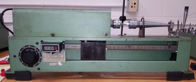
Figure 3: R.R. Moore Rotating Beam Test Apparatus With the Specimen Installed (Source: CCDC GVSC).
DATA
Data was collected for the base and FSW materials for each of those cases in the longitudinal and transverse directions. The longitudinal direction was parallel to the major rolling direction, and the transverse direction perpendicular to the major rolling direction. Figure 4 shows a comparison of the base material and friction stir in the transverse direction (BMT and FT). This plot also shows three data samples that did not fail during the testing; the machine was stopped at 25 million cycles.
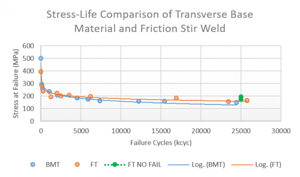
Figure 4: Stress-Life Comparison of Transverse BMT and FT Welded Material (Source: CCDC GVSC).
Figure 5 shows a comparison of the base material and friction stir in the longitudinal direction (BML and FL). This plot also shows three data samples that did not fail during testing; the machine was stopped at 25 million cycles.
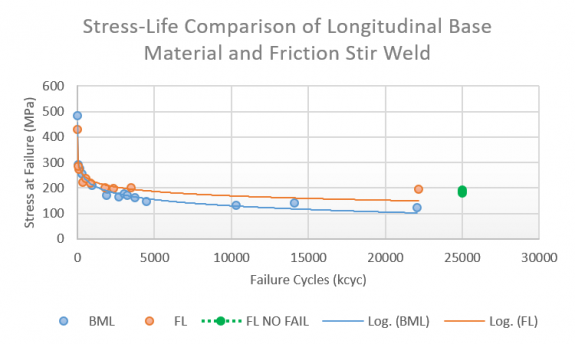
Figure 5: Stress-Life Comparison of Longitudinal BML and FL Welded Material (Source: CCDC GVSC).
CONCLUSIONS
The base material proved to be relatively consistent and predictable throughout the testing. The friction stir welded material showed a larger variance during testing. Generating data in the 10–20 million range, the cycles were difficult due to the loads selected. Some specimens would exhibit failure early, and some would continue out past 25 million cycles.
The data shows that there is a reduction in strength between the base material and friction stir welded material at low cycle fatigue; however, this trend reverses at the higher cycles. The friction stir welded material shows a higher failure stress at higher cycles, with an increase of 28% for transverse and 60% for longitudinal. This increase in fatigue is most likely due to the increase in ductility created by the friction stir process.
Looking at the S-N curves for the friction stir welded areas in both transverse and longitudinal directions, they appear to be very similar. This is an artifact of the stirring process where the grain boundaries of the material are altered by the FSW process.
Acknowledgments:
The author would like to thank Concurrent Technologies Corporation for the friction stir processing of the material and the fabrication of the specimens and Idaho National Laboratory for conducting the fatigue testing in compliance with ISO-1143.
Bibliography:
ASTM International. Standard Practice for Statistical Analysis of Linear or Linearized Stress-Life and Strain-Life Fatigue Data. ASTM E739-10, 2015.
Burguess, V. “Investigation in Friction Stir Welded Aluminum Alloy 2139-T8 for Hull Structure Applications,” 2019.
U.S. DoD. Armor Plate, Aluminum, Alloy 2139 Weldable & Alloy 2195 and 2060 Unwelded Applique. MIL-DTL-32341A, 15 April 2015.


