INTRODUCTION
The world has seen a spiraling increase in electromagnetic devices that enhance communications capabilities and place a plethora of information at any user’s fingertips. We are surrounded by electromagnetic emitters in virtually every location on the planet—from a handheld cell phone to a Global Positioning System transceiver or radio broadcast. What most people take for granted is that there are energetic-containing devices present in these environments that must function reliably when directed but not function at any other time. A prime example of this is the airbag in most modern automobiles, a lifesaver when summoned to function. However, the airbag must remain sedentary when exposed to all the electromagnetic radiation from the expected devices present in the automobile. Many hundreds, if not thousands, of development hours were expended to ensure that these conditions were satisfied before the first airbag was introduced.
This explosion of information capabilities has not been overlooked by most of the world’s military organizations. Many of these electromagnetic devices have been modified and adapted by the various militaries of the world to enhance communications, situational awareness, and target detection and perform as weapon systems, such as signal jammers and countermeasures devices. Smaller, more powerful emitting devices are fielded on military systems to enhance their offensive and defensive capabilities. Devices containing energetics must be certified as safe when operated near emitters.
The two primary methods of initiating energetic devices currently used in most systems are percussion (mechanical strike) or electrical. The main drawback to percussion initiation is that a mechanism storing an adequate amount of striking energy has to be present. The most utilized method for this is a compressed spring pushing a firing pin forward after releasing a firing retention device. The energetic device initiates when struck by the firing pin. A typical firing sequence diagram using percussion initiation is shown in Figure 1. Percussion initiation is usually a reliable mechanism, but the system pays a penalty in weight, volume, and number of moving parts associated with the striking mechanism.
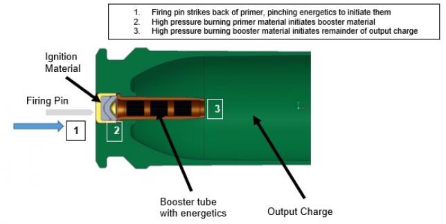
Figure 1: Typical Percussion Firing Sequence (Source: J. Hirlinger).
Modern electrically-initiated devices function via either thermal ignition (resistive heating) using an electrically-conductive material placed in intimate contact with an energetic material or exploding foils. Instead of the mechanical striking energy utilized as the initiation energy in the percussion-initiated devices, an electrical power source must be present in the system to provide the initiation energy for the electrically-initiated devices. A typical firing sequence using electrical ignition is shown in Figure 2. Electrically-initiated devices can be found in many different applications from automobile airbags to cartridge-activated devices, gun primers, detonators, and fuzes.
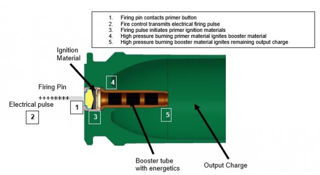
Figure 2: Typical Electrical Firing Sequence (Source: J. Hirlinger).
The main drawback to percussion initiation is that a mechanism storing an adequate amount of striking energy has to be present.
Although electrically-initiated devices are predominant and mature, they suffer from two major drawbacks. First, based upon their functional requirements, these energetic compounds are sensitive to electrostatic discharge (ESD), which presents a safety concern for workers handling the lead-based energetics. They may be vulnerable to accidental initiation due to electronic warfare (EW) attack, including a susceptibility to ESD and other electromagnetic environmental effects. Secondly, as with the percussion-initiated devices, the energetic compounds used for initiation are predominantly lead-based materials, which are considered environmentally hazardous. To minimize the environmental impacts of these hazardous materials, some international organizations enacted regulations limiting the use of environmentally hazardous compounds. For example, the European Union (EU) established a broad regulation known as Registration, Evaluation, Authorization and Restriction of Chemicals (REACH) to govern producing and using many chemical compounds. Lead has been listed in the REACH regulation as “a substance of very high concern (SVHC)” in the EU. Additionally, U.S. Department of Defense Warfighter training grounds are increasingly becoming contaminated with lead-based residues from the combustion of these devices.
WHAT IS MICRODIODE LASER IGNITION?
A microdiode laser converts an electrically-initiated device into an electro-optical one. Ignition is initiated via the same electrical input signal, but an optical output signal serves as the initiation mechanism. A microdiode laser ignition device makes three significant changes compared to most standard electrical initiators. First, the conductive element is replaced with an electrical device that creates an optical output—in this case, a microdiode laser. Secondly, the initiation energetics are removed from intimate contact with the conductive device and placed behind an optically-transparent barrier. Third, the microdiode laser ignitors function adequately with nonlead-containing energetics.
A typical firing sequence using microdiode laser ignition is shown in Figure 3. The U.S. Army Combat Capabilities Development Command (CCDC) Armaments Center is evaluating the application of these solid-state, microdiode laser devices as alternative ignition devices to traditional electrically-initiated devices. Microdiode laser initiation may offer novel solutions to many of the aforementioned technical concerns, such as reducing the use of lead-based energetics, improving resistance to evolving EW threats, reducing or eliminating mechanical moving parts during the initiation sequence, and directing “speed of light” interfacing with ignition/firing control systems.
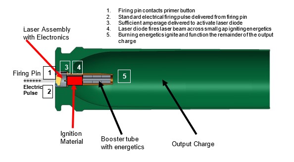
Figure 3: Typical Microdiode Laser Ignition Sequence (Source: J. Hirlinger).
Today, microdiode laser technology is ever present in our modern world of electronics. It exists in digital versatile disc players, smart phones, and low-cost laser pointers and has become a low-cost, commodity item. Microlaser diodes are incredibly small, solid-state devices that, when subjected to the proper electrical stimulus, output optical signals. Figure 4 shows a typical microlaser chip compared to a U.S. dime. The CCDC Armaments Center is interested in using simple, very low-power microlaser diodes and, in some cases, those nearly as small as the head of a pin. These devices, while separated by a translucent environmental barrier, are now physically separated from but still in close proximity (< 0.5 mm) to the energetic initiation compound. Strategically placing the laser diodes near the energetics eliminates the need for additional focusing optics to ensure ignition. This approach is best suited to one-time use, single function devices such as primers, fuze detonators, and other quick-functioning, gas-generating devices.
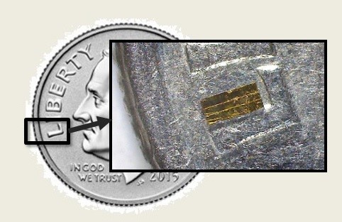
Figure 4: Microlaser Diode on a Dime (Source: S. Redington).
MICRODIODE LASER VS. OTHER LASER IGNITION DEVICES
Laser ignition has been used since the 1960s. For example, a Crusader (Figure 5, top) was modified and fired over 25,000 rounds using laser ignition, and an LW155 (Figure 5, bottom) was modified and fired over 5,000 rounds. Current laser-ignited devices utilize a remote, centrally-located, high-powered laser connected to the ignition source via a light conductive cable (i.e., a fiber optics cable). The laser is pulsed and the light transmitted through the fiber optics cable through a connecting surface, which may or may not have a focusing lens, into the initiating energetics. Microlaser ignition takes advantage of the significantly smaller size of the microdiode and places the laser source in the end item, eliminating the fiber optics cable and any focusing systems.
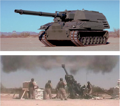
Figure 5: Two Artillery Systems Modified for Laser Ignition: The Crusader (Top) and LW155 (bottom) (Source: G. Burke).
The demands of the consumer market for smaller yet more powerful devices, from entertainment to medical, have paved the way for developing a wide variety of microlasers. Commercially-available, solid-state microlasers offer many options, including size, output power, power consumption, footprint, and wavelength. Based upon the requirements and environments of their systems, solid-state diode microlasers were developed to have long, functional lifetimes of 10,000 hours. As a result, the life expectancy for a single-use ignition device is essentially forever. As the laser device is fabricated on a silicon substrate, the base material is inert, with a very low expansion coefficient. As an example, consider the microlaser within the compact disc (CD) player of an automobile. The device sits inside the dashboard in the hot sun and freezing cold and vibrates and bounces around for many miles. Despite all of these environmental changes, the laser diode is probably the least likely of the electrical components to fail in the CD player. Microlaser devices in their current applications have already proven themselves to be comparatively low cost and quite reliable, as well as durable.
The life expectancy for a single-use ignition device is essentially forever.
Miniaturizing the laser source based upon commercial usage brings the cost and availability of these devices down to a level that makes it practical for them to be considered as single-use, “throw-away” devices. Figure 6 shows an example of a finished, sealed, single-use microdiode laser electronic assembly developed for an ammunition application. The almost limitless variety of these devices introduces a wide host of novel energetic materials for investigators to explore not only in thermal ignition methodologies, but potentially in optochemical reactions as well. As with all commodities, the cost of the microlaser is volume driven. The greater number of laser diode applications using common energetics and other components increases the demand volume, thereby decreasing individual costs.
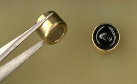
Figure 6: A Sealed, Self-Contained Microdiode Laser Ignitor (Source: S. Redington).
ADVANTAGES OVER STANDARD ELECTRICAL IGNITORS
The ability to physically isolate the energetic from the ignition source, in this case, the microlaser element, results in a unique and value-added benefit of this technology. The energetic can now be encapsulated into a laser-transparent hermetic package. This translates to a significant increase in safety of the ignitor device as it is not vulnerable to initiation by heating caused from a prolonged, low electrical current. Instead, the laser must receive the designed electrical input to pulse the laser before ignition. Lower input may cause the diode to “glow” similar to a light-emitting diode (LED). But until the threshold energy value is achieved, the diode will not function as a laser and emit the level of concentrated photons required for ignition. CCDC Armaments Center engineers have demonstrated the ability to miniaturize, seal, and environmentally package the energetic source, thus ensuring a predictable, isolated separation between energetic and laser sources governed by a laser transparent barrier. The automated robotic and compartmentalized handling of energetics eliminates the current method of physical processing by workers and inherent risks.
The unique feature of independent laser and energetic assemblies enables another advantage for this technology—the microlaser and electronic components can be manufactured by multiple, nontraditional defense contractors. The parts can be fabricated independent of the end-item application and functionally tested at multiple points within the fabrication and assembly process. The major advantage to this technique over standard electrical ignitors is that it now allows full, functional verification of the ignition source as the end-item assembly process progresses. A full, functional test of a standard electrical ignitor usually results in consuming the ignitor, thus rendering it unusable for end item application. This opens the door to multiple, competitively-based sources of supply and greater assurance of functionality at the end-item application level. Only during the final assembly stage, within the facilities of a qualified integrator of energetics-based hardware, is the microlaser electronic subassembly mated with the energetic subassembly. This approach departs radically from traditional methods for some electrical ignitors where the energetic and electronic components are mated from the very onset of fabrication. Relative to the actual fabrication process, a variety of methods can handle and process microlaser, diode-based electronic assemblies.
This technology embraces modern electronics assembly techniques such as surface mount technology (SMT). Traditionally, wire-bonding procedures are the most common way to mount a laser diode to the supporting structure in commercial applications. Refined over many years, this process is considered a mature and reliable method. Unfortunately, wire-bonding techniques may not be sufficiently robust when applied to energetics-based applications. As a result, CCDC Armaments Center developed several novel processes more suited toward military-hardened, laser-based initiation hardware.
Microlaser devices in their current applications have already proven themselves to be comparatively low cost and quite reliable, as well as durable.
Figure 7 shows an SMT in process electronics assembly board with 20 microdiode electronics subassemblies prior to final removal and packaging. To address these enhanced design requirements, CCDC Armaments Center’s goal with microlaser assemblies has been to move toward SMT processes using “tape and reel,” “pick and place,” and robotic automated assembly processes. SMT can provide a combination of microelectronics and micro-optics, providing novel hybrid “smart” initiation devices. SMT techniques can provide high reliability, precise robotic component placement, high yield, rapid assembly, lower costs, and the ability to move toward additive and flexible manufacturing techniques. Further, multiple microlaser diodes can incorporate into a single-ignitor assembly scheme, allowing redundancy to achieve greater reliability if one or more laser devices fail. The technology also allows expanding to multipoint simultaneous or sequential ignition, with the goal of delivering efficient, more-versatile, higher-output propulsion systems.
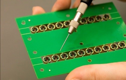
Figure 7: Surface Mounting Electronics and Laser Diodes (Source: S. Redington).
For future design applications where the firing circuit is yet to be specified, microlaser ignition via SMT manufacturing technology provides the potential integration of a host of smart features, such as a bidirectional communication link, chip identification (electronic handshake) or other user identification, temperature sensing, age, lot, and other features. All or some of these features can be added to the design as required. One of the design goals for future military systems is higher precision. Electrical ignition utilizing microlaser ignition can eliminate most of the time interval required to mechanically move components to create the required kinetic energy for ignition and the physical vibration associated with the movement and impact of these moving parts within the firing system. This leads the way toward computer-controlled/automated firing systems that allow improved coincidence based on computational analysis of range, wind, temperature, and mechanical motion of the weapon platform.
MOVING FORWARD
We need to first change how we think about our electromagnetic environment that is rapidly saturated by more and more emitting devices. In the world of explosive devices, safety is paramount. Operational workarounds are no longer practical due to the proliferation of emitting devices. We need to develop and produce fully-resistant devices that can withstand the emission of these emitters. Second, we need to overcome the reluctance to accept new technologies, especially when it comes to perturbing the long established production facilities making reasonably priced hardware. Photographic film vs. digital imagery, hard-wired telephones vs. cell phones, and cathode ray tube-based TV vs. LED/liquid crystal display flat panel TV sets are just a few historical examples of initial resistance to change that have occurred over the past 20 years (often based upon the price differential of new technology vs. existing products). Continuing to produce the same products based upon decades-old electrical ignition designs ignores the changing world around us and will eventually lead to devices that cannot be removed from their shipping containers for fear of accidental initiation from the electromagnetic environment. Lastly, there is a need to recognize that the ignitor community must move on to newer, nonlead-based compounds to serve as the ignition material. Our training grounds are fast becoming contaminated with lead-based residues as well as the work areas in the assembly facilities where workers are exposed to lead-based products daily. Microlaser-based ignition devices offer a wider variety of new and old pyrotechnic chemical products to use as substitutes for lead-based energetics.
Current experimentation in a variety of applications has shown comparable, functional results between microdiode laser ignitors and traditional electrical ignitors utilizing the firing pulse of the existing system. This means that changing over to a microdiode laser system can be accomplished without any costly changes to the current system. Will microdiode lasers completely replace all current and future electrical ignition devices? Probably not. But the encouraging results obtained so far and exploring this and other novel ignition techniques will certainly move us toward safer, more-reliable initiation devices.


