OVERVIEW
Dispersion is the scatter in fall of shot at the target due to processes which may or may not be under the shooter’s control. In general, there are two categories of error for small arms—bias errors and random errors. Figure 1 shows the effect of the two categories of errors of concern and illustrates the difference between random errors and bias errors on a target at range.
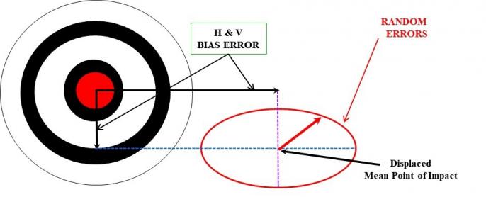
Figure 1: Random vs. Bias Error Illustration (Source: ArrowTech Associates, Inc.).
Bias errors displace the mean point of impact for a group of projectiles fired at the target from the intended impact point. Depending on the root source of the errors, the displacement of the mean point of impact can be in the horizontal plane, the vertical plane, or both planes. If the shooter or spotter can observe the fall of shot relative to the target, he or she can correct bias errors by displacing the aim point relative to the target.
On the other hand, random errors cause scatter in the fall of shot about the displaced mean point of impact. Since these errors are random, the shooter cannot successfully correct errors in this category.
The projectile and cartridge/weapon interface factors create, or help create, a tilt of the projectile principal axis and a center of gravity (CG) offset regarding the bore centerline or, in some other way, induce a projectile angular rate or cross velocity at muzzle exit, or a combination of both. The variability in magnitude and direction of the vectors comprising the error budget results in dispersion. Figure 2 shows a notional error budget for two projectiles to illustrate the variability of error budget factors in magnitude and direction.
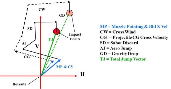
Figure 2: Notional Error Budget Vector Sum (Source: ArrowTech Associates, Inc.).
This article gives an overview of the dispersion error budget for small-caliber ammunition and identifies and quantifies the factors in the “random errors” portion of the dispersion error budget; due to space constraints, factors in the bias portion of the error budget are not covered. Factors comprising the random error budget include manufacturing defects, asymmetric engraving, the dynamic interaction between flexible bullet and a curved, flexible barrel, and blast field interactions. Bias error sources include variability in winds, drag, muzzle velocity, and weapon cant.
RANDOM ERROR BUDGET
The random error budget produces scatter of shot around a mean point of impact. Several general categories of random error attribute to the following:
- Manufacturing defects
- Asymmetric engraving
- Bullet-barrel interaction
- Bullet base – blast pressure at exit interaction
- Cartridge/weapon-related dispersion sources
- Factors related to exterior ballistics
Figure 3 shows a cross section of a projectile’s tilted axis and CG offset regarding the bore centerline.

Figure 3: Illustration of Projectile Principal Axis Tilt and CG Offset (Source: ArrowTech Associates, Inc.).
The tilted principal axis of the projectile induces an angular rate at muzzle exit. It doesn’t matter if the angle is from a manufacturing defect in the projectile or the bullet happened to be asymmetrically engraved as it travels down the bore; an angular rate will be induced at muzzle exit. Equation 1, known as the “jump equation,” is used to provide estimates of projectile jump from boresight at reasonably short ranges if the constituent inputs are known or can be readily estimated.
where
Θj = projectile jump angle with respect to the barrel centerline,
CNα = normal force coefficient derivative per sine angle of attack,
CD = drag force coefficient,
Cmα = pitching moment coefficient derivative per sine angle of attack,
Ix = projectile polar moment of inertia, Iy = projectile transverse moment of inertia,
Iy = projectile transverse moment of inertia,
m = projectile mass,
αg = projectile angle in the tube, radians,
pm = projectile exit spin rate, radians per second,
d = projectile reference diameter,
Vm = muzzle velocity, and
ΔCG = radial distance from the tube centerline and the projectile CG.
The jump equation is useful in that it provides reasonably accurate estimates for projectile dispersion if the constituent factors are known or can be estimated. It is by no means all-encompassing; however, for most small- and medium-caliber, spin-stabilized projectiles, it is fairly accurate. Large-caliber, spin-stabilized projectiles (e.g., artillery and some naval guns) use ammunition with the projectile not rigidly affixed to the cartridge case. For these systems, gravity during the projectile ramming process results in a more consistent shot-to-shot initial position of the projectile regarding the bore centerline than would otherwise result if the projectile were crimped to a cartridge case. Thus, large-caliber, spin-stabilized projectiles shoot dispersion smaller than otherwise expected.
BULLET-RELATED DISPERSION FACTORS
Bullet-related factors include the following:
- Manufacturing defects
- Asymmetric engraving
- Bullet-barrel interaction
- Bullet base – blast pressure at exit interaction
Each of these contributors will be briefly discussed next.
MANUFACTURING DEFECTS
Manufacturing defects in small-caliber bullets arises from the inability of the projectile-forming machines to make perfect projectile components.
Manufacturing defects in small-caliber bullets arises from the inability of the projectile-forming machines (typically, transfer presses) to make perfect projectile components. For a standard “cup and core” projectile where a copper jacket is drawn into a cup and a dense metal with low-yield strength is subsequently pressed into the formed jacket, any lack of concentricity of the jacket cavity with the exterior of the jacket results in a principal axis tilt and CG offset. A given defect type will result in a linear relationship between these two factors, both of which cause dispersion. The CG offset and principal axis tilt multiplied by the bullet exit spin rate cause a “throw” and “aerodynamic jump” that cancel each other out, provided the bullet CG (mass) is forward of the midpoint of the projectile bourrelet [1]. For a typical small-caliber projectile with several categories of manufacturing defects, the dispersion depends on both distribution of defect type within the lot (e.g., 55% Defect A, 35% Defect B, and 10% Defect C) and the average magnitude and distribution of defect within defect type.
ASYMMETRIC ENGRAVING
As the projectile jumps from the cartridge case to the forcing cone of the barrel, its central axis can tilt regarding the bore centerline due to clearances between the bullet outside diameter and the barrel/chamber inside diameter. In this case, even if the bullet is perfectly made, it will have an induced angular rate at muzzle exit due to the in-bore angle arising from the asymmetric engraving. Figure 4 shows several sequential photos around the circumference of a single bullet, along with the measured engraved land length on a bullet, indicating engraving asymmetry.
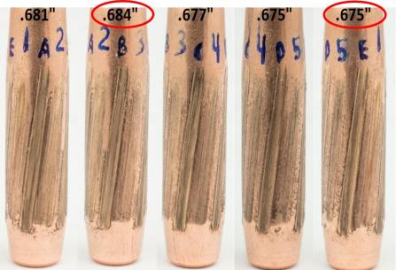
Figure 4: Example of an Asymmetrically Engraved Bullet (Source: ArrowTech Associates, Inc.).
If we take one half the difference between the maximum and minimum engraved length, divide by the average length, and then take the inverse tangent, we find that for the bullet, the engraving asymmetry caused an in-bore angle of approximately 0.38 deg. While this is a rather small angle, it is likely to have been an order of magnitude larger than any manufacturing defect that may have been present for this projectile; hence, the engraving asymmetry dominates the dispersion calculations.
BULLET-BARREL INTERACTION
Bullet-barrel interaction is a broad, catch-all type category that includes, but is not limited to, the following:
- Dynamic interaction between a flexible projectile and a curved, flexible gun tube.
- Interface between the projectile exterior and the various land geometries available.
- Free run to the forcing cone/engraving asymmetry.
The dynamic interaction between a flexible projectile and a curved, flexible gun tube causes variability in bullet exit states (cross velocity and angular rate) shot to shot. The projectile exit state’s variability arises from three sources. One source is minor differences in bullet initial conditions at first motion, both in in-bore angle magnitude and initial pointing of the weapon (around the clock as viewed from the breech). A second source is from changes in the interior ballistic-forcing function’s shot to shot affecting the peak’s in-bore deflection of the projectile structure. Shot-to-shot variation in the in-bore angle occurs as a result, even if the initial orientation of the projectile is consistent. A third source of projectile exit state variability is from asymmetric loads applied to the barrel structure by forcing the bullet to travel a curved path, causing barrel transverse motion (i.e., bore centerline pointing changes).
Figure 5 shows the “normalized” short-range dispersion observed and dispersion variation for a typical 30-cal match projectile as a function of exit twist and barrel land geometry fired from a precision weapon. The “reference” system dispersion performance is shown in the middle of the far right-hand side of the plot, the “mean” dispersion at 1.0 for the 40-cal/revolution twist rate (1/12-inch twist). If bullet CG offset and principal axis tilt were the major causes of dispersion for this system, the observed average dispersion should follow the green line diagonally upward to the left as the twist increases. Instead, the observed mean dispersion for the “standard land” barrel (solid red line) slightly decreases as the twist increases from 1/12 inch to 1/10 inch and starts upward only as the barrel twist increases from 1/10 inch to 1/8 inch.
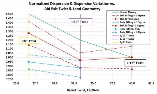
Figure 5: Normalized Mean Dispersion and Dispersion Variation vs. Barrel Exit Twist and Land Geometry (Source: U.S. Government).
Interestingly, the barrels with “polygonal” rifling geometry shoot somewhat smaller mean dispersion than the “standard” land geometry, with slightly larger variability in the 1/10-inch twist barrel. However, in the 1/8-inch twist, the polygonal barrel shoots only slightly larger average dispersion, but the dispersion variability reduces compared to the polygonal land dispersion performance in the 1/10-inch twist barrel.
The barrels with “polygonal” rifling geometry shoot somewhat smaller mean dispersion than the “standard” land geometry.
BULLET BASE – BLAST PRESSURE AT EXIT INTERACTION
Figure 5 shows that the dispersion is not purely linear with twist rate for the standard land barrel, so there must be an alternate root cause of projectile dispersion at this performance level. It was hypothesized that a source of dispersion may be from angular rate induced on the bullet by interacting a minor base asymmetry with the blast field at muzzle exit; this might not be sensitive to barrel exit twist. Immediately after muzzle exit, the bullet is in a region of supersonic “reverse flow,” where dynamic pressure from barrel emptying is very high due to the high-velocity gas. Interaction between this high-velocity gas flowing by the projectile and any asymmetry in the projectile can be a root cause of dispersion.
Figure 6 shows the flow field that develops at the gun muzzle immediately after bullet exit from the tube, along with the “Mach Disk” and the region of supersonic gas flow from barrel emptying.
![Figure 6: Muzzle Exit Flow Field Just After Muzzle Exit (Source: Klingenberg and Heimerl [2]; Reprinted by Permission of the American Institute of Aeronautics and Astronautics [AIAA], Inc.).](/wp-content/uploads/2019/11/dsiacjournal_winter2019_smallcaldisp_siewert_fig6-280x327.jpg)
Figure 6: Muzzle Exit Flow Field Just After Muzzle Exit (Source: Klingenberg and Heimerl [2]; Reprinted by Permission of the American Institute of Aeronautics and Astronautics [AIAA], Inc.).
From previous studies on the flight of spin-stabilized bullets subjected to externally applied, asymmetric loads, maximum flight path deviation occurred with an asymmetric load applied for half a bullet revolution. Extending load application past 180 deg of bullet rotation partially cancelled the early portion of the input load.
Data in Figure 7 were generated from a bullet launched from a 308 Winchester case at approximately 800 m/s. Therefore, functions published in “Phenomenology of Gun Muzzle Flow” [2] were used to estimate the location of the “Mach Disk” in time at a travel distance of 6 inches, half the nominal twist rate of the 1/12-inch twist barrel. Working through the numbers, it appears this bullet will clear the Mach Disk at about 0.18 ms.
![Figure 7: Mach Disk Location vs. Time for 7.62-mm Cartridge (Source: Klingenberg and Heimerl [2]; Reprinted by Permission of AIAA, Inc.).](/wp-content/uploads/2019/11/dsiacjournal_winter2019_smallcaldisp_siewert_fig7-455x314.jpg)
Figure 7: Mach Disk Location vs. Time for 7.62-mm Cartridge (Source: Klingenberg and Heimerl [2]; Reprinted by Permission of AIAA, Inc.).
ArrowTech’s CONTRAJ body-fixed, six degrees of freedom trajectory code was used to investigate whether blast pressure at muzzle exit could cause the observed dispersion. To assess this hypothesis, an arbitrarily selected 5-N load (simulating gas interaction with a minor flaw in the bullet boat tail) was applied at the middle of the projectile’s boat tail length (as shown in Figure 8) for the following conditions:
- A 180-deg (1/2-revolution) rotation for the 1/12-inch twist barrel, 0.18-ms duration.
- A 225-deg (5/8-revolution) rotation for the 1/10-inch twist barrel, 0.18-ms duration.
- A 270-deg (3/4-revolution) rotation for the 1/8-inch twist barrel, 0.18-ms duration.
A schematic of the externally applied load, representing the interaction of the barrel emptying flow with a minor flaw in the boat tail exterior of the bullet as it flies out through the Mach Disk, is shown in Figure 8.
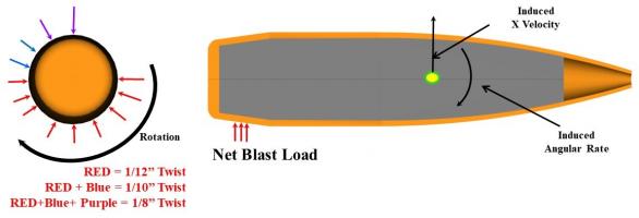
Figure 8: Asymmetric Load Application on the Projectile’s Boat Tail (Source: ArrowTech Associates, Inc.).
Two facets of the induced-flight motion caused by the asymmetric applied load on a bullet fired from barrels with different twist rates were examined—the projectile total angle of attack (AlphaBar) as a function of range (Figure 9) and the drop and drift of the projectiles vs. range (Slant) (Figure 10).
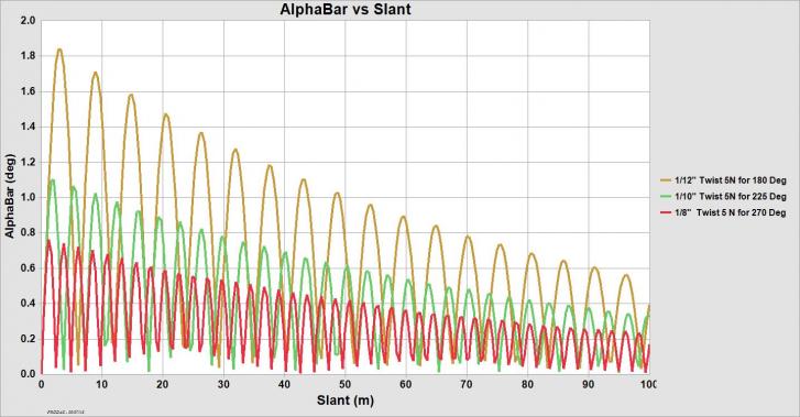
Figure 9: Angle of Attack vs. Range for Small-Caliber Bullet w/ Asymmetric Applied Load and Various Barrel Exit Twists (Source: ArrowTech Associates, Inc.).
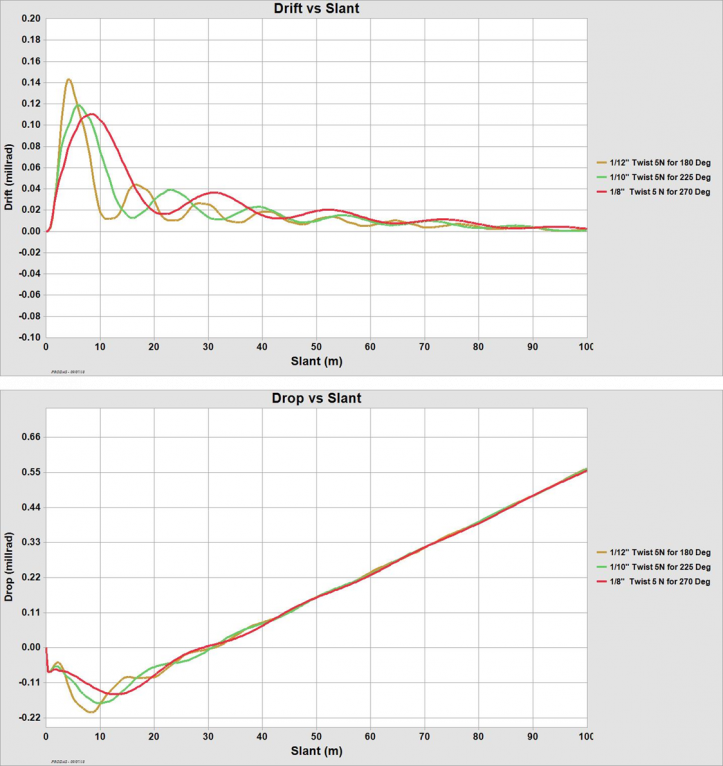
Figure 10: Drop and Drift vs. Range for Small-Caliber Bullet With Asymmetric Applied Load and Various Barrel Exit Twists (Source: ArrowTech Associates, Inc.).
Not unexpectedly, Figure 9 shows that the increased gyroscopic stability provided by the faster twist barrels, combined with the partial cancelling effect of extending the applied load past 1/2 revolution, leads to smaller induced maximum yaw levels with the faster twist barrels. The first maximum yaw for the 1/12-inch twist barrel is approximately 1.82 deg, 1.1 deg for the 1/10-inch twist barrel, and 0.75 deg for the 1/8-inch twist barrel.
This observation indicates that there will likely be less drag variability at launch from the blast pressure, asymmetry dispersion source. Interestingly, that is, in fact, what has been observed via Doppler radar during testing with barrels chambered for the same cartridge but manufactured with differing twist rates. However, the dispersion effect of a reduction in launch drag variability can only be observed experimentally at very long ranges.
As seen in Figure 10, once the bullets have flown about 70 m or so, the drop and drift caused by an externally applied impulse of fixed time duration is essentially the same for bullets fired from each barrel, regardless of the barrel twist. While this is not proof that blast asymmetry is the root cause of the observed dispersion behavior shown in Figure 5 with increasing barrel twist (e.g., lack of linearly increasing group size with increasing twist rate), it is a plausible explanation for the observed lack of linear dispersion with increasing barrel twist.
CARTRIDGE-/WEAPON-RELATED DISPERSION SOURCES
The barrel can be thought of as hollow tube with a fixity at the chamber/receiver end (for a bolt action sniper weapon with a “free-floated” barrel). If the barrel is not perfectly straight, bullet passage through the barrel causes the bullet to accelerate in a direction perpendicular to the bore axis. These lateral accelerations impose loads on both the bullet and the barrel, and the two bodies each vibrate in response to these applied loads. Since the barrel is essentially a beam element, the forced vibration imposed by bullet passage is typically expected to impose loads and deflections of consistent magnitude and direction shot to shot. However, interaction between the barrel structure and the variable pressure-time forcing function behind the projectile results in minor changes in barrel pointing and cross velocity as the bullet exits the muzzle.
CARTRIDGE
Minor differences in propellant weight, bullet weight, engraving force profile, chamber volume, free run to the rifling, and shot start pressure cause shot-to-shot variations in the attained peak chamber pressure and resulting muzzle velocity. Figure 11 shows the variability in pressure-travel performance for a typical 30-cal cartridge.
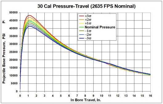
Figure 11: Mean and Sigma of Pressure Time for 30-cal Projectile (Source: ArrowTech Associates, Inc.).
The variation in shot-start pressures and in-bore travel time causes the barrel to point in a slightly different direction and have a slightly different cross velocity for each shot at bullet exit from the muzzle, contributing to dispersion. For high-quality barrels, this shot-to-shot variation is small, and it is the reason shooters are willing to pay more for a high-quality barrel.
Free floating the barrels has the following two beneficial effects when it comes to keeping group sizes small:
- It reduces the first bending mode frequency of the structure, making it easier to avoid resonance between projectile spin and barrel bending.
- It prevents barrel thermal expansion from firing multiple shots in rapid succession and significantly altering the barrel pointing vector.
WEAPON
Several weapon factors can influence the dispersion of ammunition, most of which are related to the interface between the bullet and the barrel. Figure 12 shows a comparison of bourrelet length for a typical match bullet for a barrel with a 0.3013-inch-diameter land and one with a 0.2980-inch-diameter land. The barrel with the smaller land diameter provides a longer bourrelet (~7% longer) and a smaller in-bore angle for the bullet when a fixed in-bore clearance between the bullet bourrelets and the barrel lands is assumed. As seen in Equation 1, projectiles fired with smaller in-bore angles are expected to exhibit smaller aerodynamic jump—all else are equal.
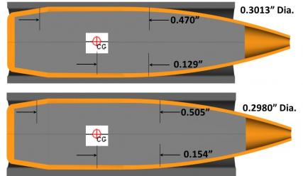
Figure 12: Comparison of Bourrelet Length vs. Land Diameter (Source: ArrowTech Associates, Inc.).
Since there must be clearance between the interior dimensions of the weapon chamber and the exterior dimensions of the cartridge case to ensure the bolt will close on the chambered ammunition, it is nearly impossible to have the projectile centerline precisely aligned with the bore centerline as the cartridge is chambered. (This condition is illustrated in Figure 13.)
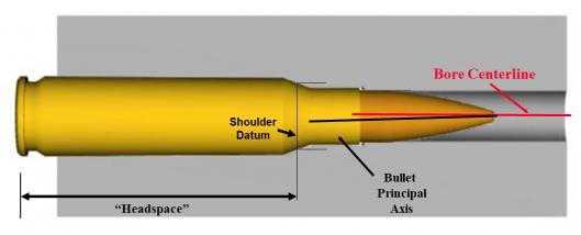
Figure 13: Bullet-Bore Centerline Alignment Comparison (Source: ArrowTech Associates, Inc.).
Fortunately for the shooter, the projectile can act in a sufficiently elastic manner to provide a “self-centering” alignment as it starts moving down the barrel, provided “free run” to the rifling is short and the pressures/accelerations at the start of engraving are reasonably low.
As the bullet makes the jump from the cartridge case into the barrel-forcing cone, the details of the projectile structure, the materials from which the bullet structure is comprised, and the stress-strain behavior of projectile materials all play a part in the ultimate plastic deformation of the projectile structure and symmetry. For lead core-copper jacketed bullets, the stresses in the jacket can be quite high early in the in-bore travel, leading to asymmetric yielding of the jacket. For this reason, lead core-copper jacket bullets typically shoot smallest dispersion when the bullets are loaded very close to the barrel lands. This limits plastic deformation of the projectile structure early in the in-bore travel as the bullet does not have to move very far for the barrel to provide structural support to the projectile structure.
On the other hand, monolithic copper projectiles can tolerate a bit more “free run” to the rifling than a lead core-copper jacketed bullet because the density of projectile body is much lower than lead and the yield strength is considerably higher than lead. As a result, monolithic copper bullets typically shoot the smallest dispersion, with free run of about 0.020–0.050 inches (0.5–0.1.3 mm).
SUMMARY
The factors affecting small-caliber bullet dispersion as a result of sources originating during projectile travel while inside the barrel have been identified and discussed. All the dispersion sources discussed so far influence the “random” portion of the error budget. For random dispersion sources, all these effects must be added up in a root-sum-square manner to estimate the group size at range unless error source measurement resolution is unavailable to all but the most exacting test facilities.
The angular rate induced by interaction between the flow field created by barrel emptying and any bullet base asymmetries is expected to show very limited sensitivity to the barrel exit twist due to the fixed time duration of asymmetric load impulse application and the flight dynamics of the projectile in response to increased exit spin rates. Dispersion from this error source is typically only visible to the shooter at the very smallest dispersion levels.
The relative magnitudes of each of these errors depend on many factors, some under the direct control of the bullet maker, some affected by the ammunition maker, and some affected by the barrel/weapon maker. The manufacturers of each component of the weapon system must do their part to make the total system error as small as possible to successfully push the system hit probability as high as possible.
References:
- McCoy, R. Modern Exterior Ballistics. Atgen, PA: Schiffer Publishing, pp. 252–267, 1999.
- Klingenberg, N., and J. M. Heimerl. “Phenomenology of Gun Muzzle Flow.” In Gun Muzzle Blast and Flash, AIAA, vol. 139, 1992.


