Introduction
The prolific use of the improvised explosive device (IED) in recent years by enemy combatants has forced U.S. combat vehicle designers, testers, and analysts to focus on protecting military vehicles and their occupants as never before. The IED threat, assembled from readily available ingredients, is relatively cheap to construct and employ. It thus poses a significant threat to troop mobility and military personnel safety.
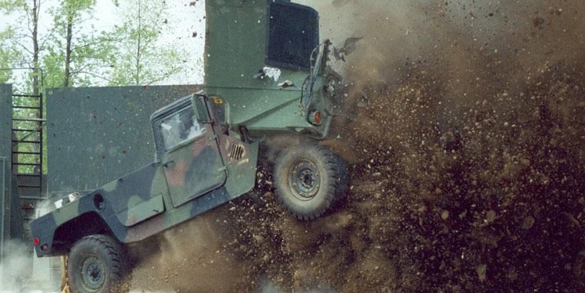
Consider the violent chain of reaction resulting from an IED detonated when driven over by a military vehicle (such as shown in Figure 1). The explosion produces a supersonic pressure wave that propagates through the soil, sending a combination of high- velocity dirt, rock, and air smashing into the truck’s underbody. The vehicle’s mobility is often an assumed casualty of this event. Shock waves quickly ripple through the vehicle before military personnel inside are even able to react.
The ultimate effect on these personnel, of course, is dependent on numerous factors, including the size of the explosion and the design of the truck. However, the range of possible personnel injuries can vary from complete protection (i.e., no injury) all the way to severe injury and loss of life for some or all of the occupants. While it is true that not even the best military vehicle on today’s market can protect occupants against large, overmatching explosions, it is equally true that the way a vehicle is designed to protect against such attacks can literally save lives.
This article briefly describes the recent history and theory of protecting occupants within armored ground vehicles against underbody blast (UBB) attacks while using the upcoming Joint Light Tactical Vehicle (JLTV) (such as the one pictured in Figure 2) as a case study of a recent application of a truck designed to offer both high mobility and high occupant protection from UBB.
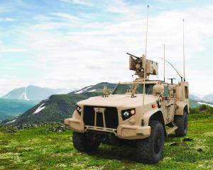
Figure 2: The JLTV (Oshkosh, CC BY-SA 4.0 via Wikimedia Commons).
The Rise of the MRAP
UBB attacks quickly became a significant problem to U.S. troops entering Iraq and Afghanistan in the early 2000s [1, 2]. Enemies fashioned IEDs using homemade materials, allowing the explosives to be large in size and widespread in usage. The traditional High-Mobility Multipurpose Wheeled Vehicle (HMMWV)—commonly referred to as the Humvee—that was used for ground transport was clearly not suited to protect against these sorts of attacks [3]. Thus, the U.S. military rapidly issued the production and delivery of new Mine Resistant Ambush Protected (MRAP) trucks (such as those shown in Figure 3). These trucks quickly proved to be highly successful in providing the much-needed UBB protection [4].
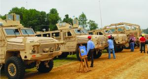
Figure 3: The MRAP Solution for the UBB Problem (U.S. Navy Petty Officer 2nd Class Molly Burgess).
Key features that have led to the success of the MRAPs include their high ground clearance, V-hull design, strong crew capsule, and energy-attenuating seats and floors. However, MRAPs weigh in at approximately 30,000 lbs, and thus they are less agile than 8,000-lb HMMWVs. So the military identified the need for a vehicle that affords the protection level of an MRAP but with the mobility of the HMMWV. Enter the JLTV.
The Genesis of the JLTV
The JLTV program was officially approved in November 2006, and a request for proposals (RFP) was put out to vehicle developers in 2008 [5]. Numerous developers competed for the work, but eventually the Oshkosh Corporation was awarded the contract in 2015 to design and fabricate JLTVs for the U.S. military [6].
Oshkosh’s JLTV will soon undergo official live fire test and evaluation. The testing will, in part, consist of a buried explosive being detonated beneath the vehicle. Inside the JLTV will be anthropomorphic test devices (ATDs) (like those shown in Figure 4), which are designed to measure responses that a human occupant would sustain. The JLTV will be evaluated by how it protects occupants (or, in this case, ATDs) against UBB in these tests.
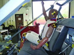
Figure 4: ATDs in a Vehicle to Simulate/Measure Human Occupant Responses (University of Virginia,
National Highway Traffic Safety Administration).
Due to the sensitive and proprietary nature of the JLTV’s specific designs, a detailed dissection of its underbody protection cannot be provided here; however, the following sections highlight the top-level characteristics of the JLTV and describe the general means by which these characteristics protect occupants against UBB.
High Ground Clearance
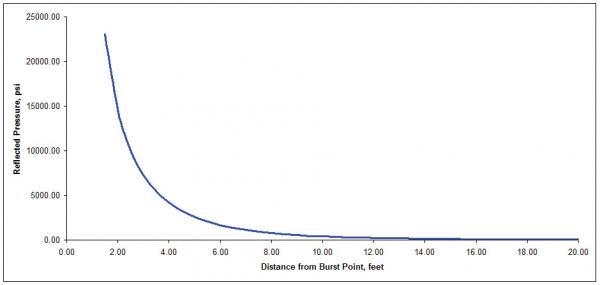
In terms of UBB protection, air is a cheap and potent help. As illustrated in Figure 5, the distance between the source of an explosion and the truck is critical, as pressure decreases rapidly as a function of distance [7]. So every inch that can be afforded to increase the distance of a truck’s underbody from a buried explosive yields a major protection benefit.
The JLTV features large tires and a suspension that gives its hull a high ground clearance, comparable to the approximately 2- to 3-ft ground clearance for MRAPs. By contrast, the HMMWV has a clearance of only about 14 inches from the ground to the bottom of its hull.
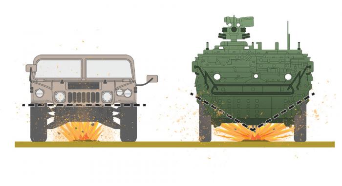
MRAPs have also benefitted in standoff by way of their noteworthy V-shaped hull. The ground clearance is, of course, lowest for UBB detonations beneath the center of the V-hull, but for off-center detonations, the effective ground clearance increases as a function of the angle of the V-hull. Although the specific hull shape of the Oshkosh JLTV cannot be discussed at this point, it is expected to incorporate the same sort of benefits as the MRAP’s V-hull (even if it does not perfectly replicate it).
Strong Crew Capsules
In addition to offering increased ground clearance for off-center detonations, the V-hull design used in MRAPs also provides occupant protection from UBB due to the V-hull’s structural rigidity. Just as pitched roofs on houses provide more support against collapse than flat roofs, so the V-shape strengthens the truck’s hull better than flat-bottom hulls. The loading to the V-hull from the UBB is distributed to the vehicle side walls, whereas on a flat-bottom vehicle, the loading primarily forces the flat hull to bend, inducing seam failure or hull rupture (see Figure 6).
A common myth about the V-hull is that its main beneficial effects for UBB protection are in deflecting the blast. In reality, however, the blast’s pressure wave is imparted to the vehicle hull regardless of its shape. The primary benefits of the V-hull shape come from the previously mentioned increased ground clearance and increased structural rigidity that the V-hull offers.
Nonetheless, the hull is typically the truck’s first component to be impacted by the fast-moving pressure wave. Thus, it must be strong enough to resist deformation or rupture. The hull of a basic HMMWV is relatively thin and prone to rupture even against a small charge, while the MRAPs and JLTV have much thicker, stronger hulls.
It is also important to ensure that the rest of the crew capsule is robust enough to handle the loading being sustained by the hull. This requirement means that the side walls and roof must be securely attached. Attachment methods may consist of bolted or welded connections; some MRAPs even use a seamless monocoque hull. For the JLTV, Oshkosh primarily uses thick bolts to hold the crew capsule together.
Another key principle in this regard can be related to a popular school physics experiment, wherein students are tasked to design a capsule to protect an enclosed egg from a high drop. Good egg-drop designs follow the simple principle of having a strong outer layer and then soft inside components to absorb the shock. Similarly, a good truck design should have both a strong outer shell and absorbent components inside (as discussed further in following sections) to protect the occupants. And the JLTV design has just that.
Energy-Absorbing Floors and Blast Mats
Given a sufficiently resilient crew capsule, the occupants inside are then protected by mitigating the shock wave from producing severe loads to the floor that the occupants’ feet are placed on and to the seats in which the occupants are seated.
The foot/lower-leg is the main impact point to an occupant in UBB attacks (see Figure 7), and elevated loads to the floor can induce serious injuries to the foot and lower leg. To protect against these injuries, the forces passed to the floor and then the occupants’ feet must be mitigated. Methods to disconnect or “float” a floor from the rest of the crew capsule or hull have been effectively used in MRAPs [8]. Additionally, it is helpful to move the point where the floor is connected to the crew capsule as far upward and away from the source of the UBB as possible.
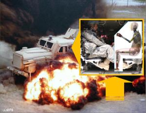
Figure 7: The Highly Vulnerable Leg in UBB Events (Photo Courtesy of the U.S. Army and Diversified
Technical Systems Inc.).
Ultimately, the key to good floor designs is in breaking up the load path so there is not a direct means of transmitting the full shock wave encountered by the hull to the walking floor. By contrast, the floor that occupants place their feet on in HMMWVs is the same as, or directly attached to, the hull exposed to the UBB. The JLTV’s particular methods of mitigating forces to the floor are proprietary, but it is reasonable to assume that designers have learned from MRAP design and testing the importance of ensuring that the floor receives as little of the shock wave as possible to protect the occupants’ lower legs.
Blast mats have also proven themselves to be an easy and effective add-on to further reduce forces to the occupants’ feet and lower legs. These mats, which are simply placed on the floor between the occupants’ feet and the walking floor, are designed to further absorb the injurious loading that makes its way to the walking floor. The mats function by compressing under high loading. To this end, the thickness of the mat is a key characteristic of its utility. The amount and rate of compression is dictated by the mat’s internal structure. For example, SKYDEX mats, which have been included in thousands of MRAPs [9], absorb energy via compression of their hemispherical cells [10] (see Figure 8). Once again, the specific mat used in the JLTV is proprietary, but it is expected to feature a specially designed blast mat that further protects occupants from injurious loading to the feet and lower legs.
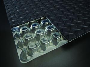
Figure 8: Energy-Absorbing Blast Mats (Photo Courtesy of Viconic Defense).
An alternative and highly effective method of protecting lower legs is to keep feet off the floor completely, such as via a foot rest. Some methods of incorporating foot rests integrate them into seats [11, 12] (see Figure 9). However, foot rests built into seats have been found to create a ride comfort issue, forcing occupants to tuck their feet up onto their foot rests or outstretch them onto foot rests on opposing occupants’ seats. In both cases, the posture can be difficult to endure for long trips. In addition, even with foot rests, attention must first be paid to designing a quality floor for the inevitable cases in which foot rests may not always be used and feet are placed on the floor during an UBB attack.
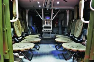
Figure 9: Protective Measures for Occupant Legs in UBB Events.
Energy-Absorbing Seats
In addition to the floor, the other main point of contact between a seated occupant and the vehicle is the seat itself. The primary principle to protect occupants from forces to the floor also applies to the seat: mitigate the shock wave running through the crew capsule using energy-attenuating devices in the load path to the occupant. This mitigation can often be accomplished by mounting the seats to the side walls or roof, as far from the UBB as possible.
Furthermore, whether floor- or wall-mounted, seats are generally designed as standalone systems with their own energy absorption mechanisms. Like blast mats, energy-absorbing seats (such as those shown in Figure 10) generally function by compression of some component. Examples of components designed in seats to absorb energy include a crushable link built into the frame, a wire or rope holding the seat designed to stretch, and a flared tube designed to narrow by the stroke of a movable collar.
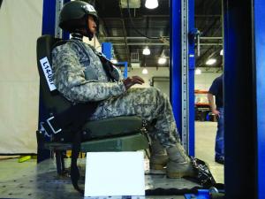
Figure 10: Current Blast-Attenuating Seats (Photo Courtesy of Viconic Defense).
Additionally, the aid of a compressible seat cushion should never be overlooked, as a thick foam can dissipate much energy before that energy reaches an occupant. Finally, more exotic energy absorption methods, such as using magnetorheological fluid (a fluid that can provide dynamic damping as a function of a magnetic field applied onto it) for seat protection measures, have also been the topic of some research [13, 14, 15, 16]. HMMWV seats were not designed with blast attenuation in mind, and so they typically consist of generic automotive seats mounted to the floor. The JLTV, however, is expected to incorporate seating systems specially designed to absorb shock loads from UBB.
Multi-Point Seat Restraints
Seating restraints are also an important element to occupant protection from UBB. The primary shock loading from a UBB will often induce gross motion of the vehicle and occupants such that, without seating restraints, occupants may be tossed around the vehicle and thus be susceptible to head or limb injuries from impacting the surrounding structure. Seat restraints do not need to have a special blast-attenuating design; they serve the occupant best by simply keeping the occupant in the seat while a vehicle is launched into free flight from a UBB. That said, most seats in military trucks such as MRAPs, HMMWVs, and (likely) the JLTV, use four- or five-point seat harnesses to more securely restrain occupants than typical automotive seat belts/restraints.
Active Protection Systems
As discussed previously, a UBB rapidly imparts an initial force/velocity to a vehicle, often sending it up into the air and then back to the ground. The velocity of the vehicle when it returns to the ground is, of course, controlled by the rate of gravity and thus is a function of the max jump height. Accordingly, active countermeasure systems (such as shown in Figure 11) have been proposed to reduce the vehicle’s max jump height and its return-to-ground velocity to soften the impact and protect occupants from sustaining additional injuries (beyond what may have already been incurred during the initial launch of the vehicle). The systems reportedly can sense and rapidly activate externally mounted thrusters to limit the max motion and control the rotation to prevent rollover [17]. Unfortunately, although these systems may prove to limit rigid-body response, the act of “pushing back” against the UBB may actually increase localized loading to the vehicle. Thus, before these active countermeasure systems are fielded, ongoing research and development will need to test and analyze the positive-negative tradeoffs that come with them. Currently, there is no reason to expect the JLTV to don such active countermeasure systems, but they remain a promising technology that is being researched for future concepts.
Conclusion
The U.S. military has learned much about protecting occupants from injuries against UBB. The combat-tested MRAPs have proven that ground vehicles with a high ground clearance, strong crew capsule, and energy-absorbing mechanisms (such as floors, mats, and seats) can successfully save lives against UBB. The JLTV is expected to take all of these survivability-enhancing characteristics and apply them to a faster, more agile vehicle. As a result, U.S. troops are expected to be both better protected and more mobile as they complete their missions.
References:
- Wilson, Clay. “Improvised Explosive Devices (IEDs) in Iraq and Afghanistan: Effects and Countermeasures.” Congressional Research Service Report for Congress, 28 August 2007.
- Bird, Sheila M., and Clive B. Fairweather. “Military Fatality Rates (by Cause) in Afghanistan and Iraq: A Measure of Hostili- ties.” International Journal of Epidemiology, vol. 36, no. 4, pp. 841–846, 2007.
- Turnbull, Grant. “End of an Icon: The Rise and Fall of the Humvee.” Army-Technology.com, http://www.army-technology.com/features/featureend-of-an-icon-the-rise-and-fall-of-the-humvee-4381884/, published 30 September 2014, accessed 7 February 2017.
- Vanden Brook, Tom. “Gates: MRAPs Save ‘Thousands’ of Troop Lives.” USA TODAY, http://usatoday30.usatoday.com/news/military/2011-06-27-gates-mraps-troops_n.htm, accessed 7 February 2017.
- Feickert, Andrew. “Joint Light Tactical Vehicle (JLTV): Background and Issues for Congress.” Congressional Re-search Service Report for Congress, 9 September 2016.
- Gould, Joe. “Oshkosh Wins JLTV Award.” Defense News, http://www.defensenews.com/story/defense/policy-budget/industry/2015/08/25/oshkosh-wins-jltv-award/32278319/, published 25 August 2015, accessed 7 February 2017.
- Walbert, James N. “An Overview of Blast and Its Effects on Combat Systems.” SURVICE Monograph 13-001, SURVICE Engineering Company, May 2013.
- Defense Industry Daily. “MRAP Advance Purchase #2: Oshkosh, PVI & GD.” http://www.defenseindustrydaily.com/mrap-advance-purchase-2-oshkosh-pvi-gd-03104/, 6 March 2007, accessed 7 February 2017.
- Business Wire. “SKYDEX, Oshkosh Sign Multiple Agreements to Install Blast Mitigating Flooring in More Than 1,400 Vehicles.” http://www.businesswire.com/news/home/20110621007332/en/SKYDEX-Oshkosh-Sign-Multiple-Agreements-In-stall-Blast, accessed 7 February 2017.
- Jiang, Binhui, Feng Zhu, Xin Jin, Libo Cao, and King Yang. “Computational Modeling of the Crushing Behavior of SKYDEX® Material Using Homogenized Material Laws.” Composite Structures, vol. 106, pp. 306–316, December 2013.
- Jankel Tactical Systems. “BLASTech Seating.“ http://www.jankelts.com/static/images/BLASTech11_371.pdf, published June 2013, accessed 7 February 2017.
- Med-Eng. “Crew/Troop Blast Seats.” https://www.med-eng.com/products/crewsurvivability/blastattenuationseats/crewtroop.aspx, accessed 7 February 2017.
- Wereley, Norman W. “Particle Simulation in Magnetorheological Flows.” Presentation, University of Maryland GPU Summit, https://obj.umiacs.umd.edu/gpusummit/slides/Norman_Wereley_UMD.pdf, accessed 7 February 2017.
- Choi, Young-Tai, and Norman M. Wereley. “Mitigation of Biodynamic Response to Vibratory and Blast-Induced Shock Loads Using Magnetorheological Seat Suspensions.” The American Society of Mechanical Engineers, http://proceedings.asmedigital-collection.asme.org/proceeding.aspx?articleid=1589206, accessed 7 February 2017.
- Phys.org. “Army Looks at Improving Vehicles’ Performance With MR Fluid Technology From Lord Corporation.” https://phys.org/news/2004-07-army-vehicles-fluid-technology-lord.html, accessed 7 February 2017.
- Sun, S. S., D. H. Ning, J. Yang, H. Du, S. W. Zhang, and W. H. Li. “A Seat Suspension With a Rotary Magnetorheological Damper for Heavy Duty Vehicles.” IOPscience, http://iopscience.iop.org/article/10.1088/0964-1726/25/10/105032/meta,accessed 7 February 2017.
- TenCate. “Active Protection System.” http://www.tencate.com/emea/advanced-armour/abds/default.aspx, accessed 7 February 2017.


