


Introduction
With dominance of the electromagnetic (EM) spectrum increasing in importance and U.S. military vehicles and systems being faced with an array of threats from various adversaries, control and management of the EM spectrum will determine where future battles are won or lost. Simultaneously, the use of unmanned aerial systems (UASs) in the battlefield for surveillance, targeting, and weapons delivery continues to rise.
The UAS is an aerial electronics platform that can fly without a pilot physically located in the aircraft. It consists of an airframe and a computer system that combines sensors, Global Positioning Systems, servos, central processing units, and sometimes a weapon delivery system. With a configuration like that illustrated in Figure 1, all the elements combine to yield a platform without any direct human intervention that can operate in an autonomous manner controlled from the ground. UAS size, type, and configuration vary depending on the application. These can be large vehicles which rival the size of small, manned vehicles and small enough to be launched by hand or via a portable launch tube.
![Figure 1. Representative UAS Configuration <em>(Source: Pastor et al. [1]).](https://dsiac.dtic.mil/wp-content/uploads/2025/02/luzetsky-figure-1_762f16.png)
Figure 1. Representative UAS Configuration (Source: Pastor et al. [1]).
Considering the heavy reliance on electrical and electronic systems for operation being critical to UAS platforms’ success in and control of the modern battlefield, EM hardening of the electronic/electrical systems and protection from external EM events/threats are paramount. Without protection, UAS vehicles can easily be lost, endangering personnel relying on them for information and/or direct battlefield support through armament delivery. Loss can occur through disruption of the communication link as well as through an upset of electrical and electronic systems critical to vehicle operation. Although circuit architecture can be used to mitigate some of the effects, these techniques can be costly, adversely impact system weight, and may be unable to address all aspects of the EM spectrum. Therefore, additional techniques are required to provide protection to operate successfully in the modern battlefield, especially considering the ever-increasing energy levels associated with modern battlefield threats that can generate electromagnetic pulses (EMPs) and high-power microwaves (HPMs).
EM Threats
The EM spectrum can be challenging for electronics and electrical systems. EM effects can cause upsets and hard failures of electronics and produce power surges that can damage electrical and communication networks. Elements of the EM spectrum provided in Table 1, where an EMP is a major player, identify the threats that comprise the spectrum and possible sources of EM radiation.
Table 1. EM Spectrum (Source: H. R. Luzetsky)
Furthermore, the EM threats identified in Table 1 are frequency dependent and require differing shielding levels, as identified in Table 2.
Table 2. Frequency and Shielding Ranges for EM Threats (Source: H. R. Luzetsky)

There are two main paths taken by EM radiation to couple with electronics and electrical systems—front and back door coupling. Front door coupling refers to entrances along the ports and openings designed for transmitting EM energy either conducted directly or radiated to communicate with the outer environment. These ports and openings include antennas and sensors designed to communicate with the exterior environment.
Back door coupling refers to those EM entrances not intended for communication with the exterior environment. These entrances include perforations and penetrations associated with cable and mechanical pass-throughs required in designing the UAS. When considering the paths for EM radiation coupling with electronics and electrical systems, entrances can be physical (hole, penetrations, cable runs, etc.) as well as solid (side walls with no EM mitigation properties).
EM Threat Protection
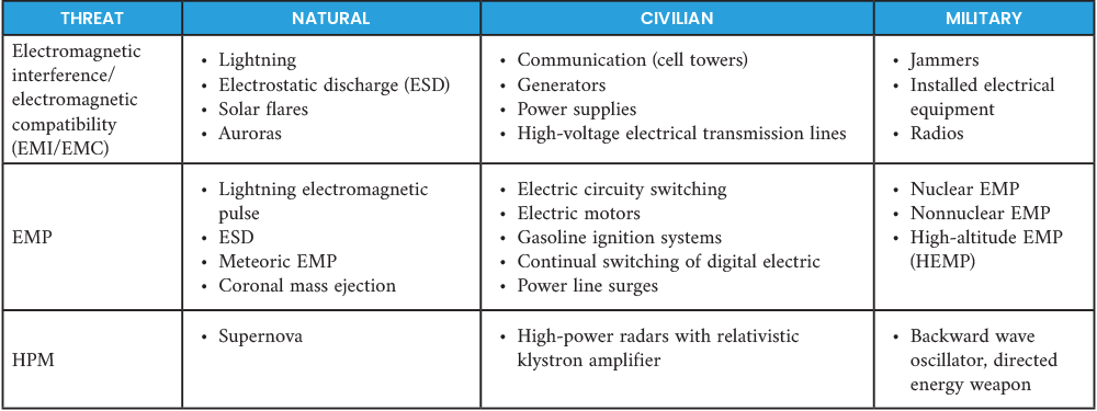
Protection of electronics and electrical systems typically uses a layered approach (as illustrated in Figure 2), consisting of isolation, EM shielding and filtering, surge protection, and grounding [2]. Of these layers, EM shielding is the most effective for a UAS. Isolation is impractical while filtering; surge protection and grounding are the last lines of defense—coming into play once energy from an EMP penetrates outer protection layers, impacting the electrical and electronic components. With appropriate EM shielding, the EMP can be stopped or significantly reduced before reaching the electrical and electronic components. Any remaining EM threats can then be easily addressed by filtering, surge protection, and grounding.
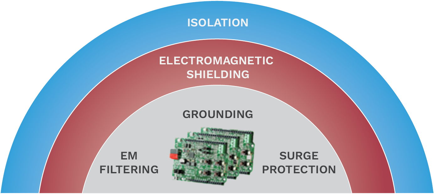
Figure 2. EM Protection Layering for Electronics and Electrical Systems (Source: H. R. Luzetsky).
For UAS platforms, providing protection to safeguard electrical/electronic systems against these threats for reasonable weight can be a challenge since the UAS structure is a simple, lightweight, aerodynamically efficient, and stable platform with limited space for avionics and payloads. To address the hardening of UAS platforms to the growing EM modern battlefield, assessments of UAS platforms against current and future EM environments have been gaining impetus and importance. Assessments have shown that current UAS platforms do not possess the EM protection needed to circumvent damage or potential loss from high-energy EMP events, and their electronic systems are vulnerable to disruption, upset, and even destruction. With vulnerabilities defined, efforts are ongoing to develop solutions that target those vulnerabilities, reducing them and improving vehicle survivability.
In addition, due to the operational characteristics of UAS platforms, there is a need to transmit and receive across specific frequencies and remain open to support the various operations. This translates to a need to create either transient or permanent frequency windows of transparency within the platform. Creating a shielded structure around the electronics and electrical systems of a UAS platform provides an overall level of EMP protection for the enclosed systems. Systems like sensors and antennas would be mounted to the exterior of the protected area to support unrestricted transmission and receipt of information necessary for the UAS platform operation. External equipment connected to internally protected systems through shielded cables represents a pathway for EMP radiation to reach the internal systems and must then rely on EM filtering and surge protection to defeat the threat.
The key aspect to providing EM threat protection is enclosing a critical electrical and electronic system within an EM shielded structure to provide a baseline level of protection and then handling the penetrations like cabling with other techniques such as EM filtering and surge protection. The difficultly for UAS platforms is that traditional methods of protection to achieve levels defined in Table 2 are thick metal enclosures like 0.125-in-thick aluminum, which tends to be a parasitic weight not tolerated by a UAS platform because of the impact to its operational capability. Efforts have been and are still ongoing to develop composite and polymeric materials with integrated EM shielding. These types of materials provide a means to integrate EM into a UAS platform without incurring significant weight growth to the system.
Material With Integrated EM Shielding
Numerous efforts exist to develop lightweight EM shielding solutions for aircraft structures, with a focus on electronic enclosure boxes. A review of existing techniques has been conducted through a Defense Systems Information Analysis Center report (Figure 3), which highlights EM protection levels afforded by current metal and composite materials [3]. Levels achievable with current materials were observed to be significantly less than that required to protect against threats identified in Table 2.
![Figure 3. EM Shielding Effectiveness of Different Materials (Source: Piner et al. [3]).](https://dsiac.dtic.mil/wp-content/uploads/2025/02/luzetsky-figure-3.jpg)
Figure 3. EM Shielding Effectiveness of Different Materials (Source: Piner et al. [3]).
Developmental efforts to enhance EM capability have been largely centered on additives to formable thermoplastics to enhance EM shielding and electronic approaches like EM filters and active surge protectors. These efforts continue to fall short of the protection requirements identified in Table 2. In addition, application of these solutions still tends to add parasitic weight to the vehicle. For UAS platforms with no room for weight growth, this often results in omission of any EM protection, which can be devastating in the modern commercial and battlefield environment.
Reconciliation of weight with required EM shielding involves developing a multifunctional material that provides structural properties suitable for constructing a UAS while providing EM shielding capable of meeting the shielding requirements specified in Table 2. A recently developed, multifunctional, composite material form originally made for an electronic enclosure box provides a way to achieve high levels of EM shielding with minimal, if any, weight impact to an aircraft structure, particularly for a UAS.
Multifunctional Composite Material Development
A multifunctional composite material with integrated EM shielding suitable for application to a UAS structure was initially developed under a U.S. Air Force (AF) Small Business Innovation Research (SBIR) program AF 131-110, titled “Electromagnetic Hardened Composite Enclosures for Aircraft Systems” [4]. The material was developed from a graphite-reinforced composite in which expanded copper mesh was integrated using a specially designed in situ tape placement head. In the manufacturing process, the raw material is heated using a laser heat source and consolidated/compacted with a rigid steel roller. The process, illustrated in Figure 4, relies on the combination of localized heat and pressure from the compaction roller to consolidate the laminate. This process is critical to achieving intimate contact between the graphite fibers and copper mesh to reach the levels of conductivity necessary to support high levels of EM shielding.
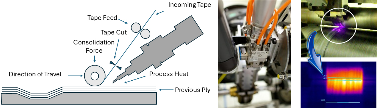
Figure 4. In Situ Automated Fiber Placement (AFP) Process With Laser Heat Source (Source: TSS/Albany).
In the original AF SBIR AF131-110, an electronic enclosure was created at ~25% the weight of a representative metallic enclosure (~1/8-in-thick aluminum), demonstrating an EM shielding effectiveness equivalency. The measured shielding effectiveness of the developed material was approximately between 90 and 135 dB, depending on frequency. Below 1 MHz, measured values were between 120 and 135 dB; from 1 to 10 MHz, measured values were between 135 and 90 dB; from 10 MHz to 10 GHz, values were between 90 and 110 dB; and over 10 GHZ, values were between 110 and 120 dB. Current EM-shielded, nonmetallic enclosures exhibit EM shielding effectiveness levels between 30 and 70 dB, depending on frequency (Figure 3), which is significantly less than that exhibited by the developed material under AF131-110.
From this initial development, material properties were examined. The impact to mechanical properties was minimal. In combination with the in situ tape placement, the material was adaptable to an aircraft structure. Efforts moved forward to demonstrate the capability for providing structural and EM shielding properties suitable for a UAS.
Recently completed, developmental research with a multifunctional composite material has provided a technique and approach for expanding the shielding levels of a UAS fuselage to levels equal to metallic construction at a fraction of the weight. This enhances their capability in the modern EM battlefield. In addition, the additive manufacturing process creates the potential to increase these levels even further with discrete placement and quantity of select materials and their forms into the base laminate. Due to the multifunctional aspects for the developed material form and the manufacturing integration process, custom-designed structures can be developed. This is demonstrated with a representative UAS fuselage with shielding integrated into those areas protecting the electronics and electrical systems.
The developed, multifunctional composite material consisted of an intermediate modulus graphite fiber (IM7)/polyetheretherketone composite with integrated, expanded copper mesh discretely placed within the composite laminate. This is shown in a cross section of the material in Figure 5. Through evaluating various laminate configurations, it was determined that the number and location of mesh layers within the laminate impact the EM shielding and mechanical property characteristics.

Figure 5. Magnified Cross Sections of Multifunctional Material (Source: H. R. Luzetsky).
Computerized tomography (CT) scans were used to evaluate the condition of the as-processed copper mesh in the laminate, including distortion, overlaps, and variation of mesh openings from processing. Multiple CT scans were conducted with a voxel size of 2.14 µm or 8.4 µm.
Figure 6 shows the CT images that illustrate the general configuration of the as-processed mesh. While the general shape of the copper mesh was retained, it was observed that the fabrication process tended to elongate the mesh along the 0° direction, altering the short-way-of-opening dimension. In addition, there was a slight reduction in the size of the overlap in certain areas; however, the tape overlaps were present, as designed.
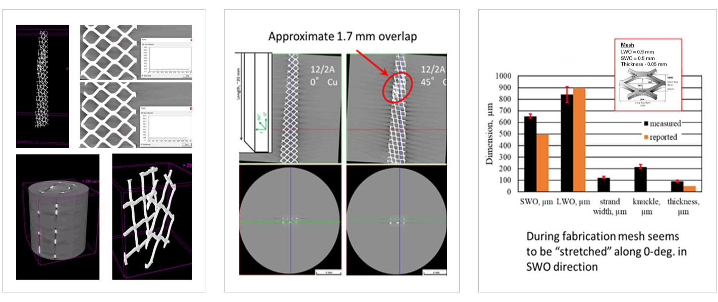
Figure 6. CT Scans Illustrating Copper Mesh Configuration in the Laminate From Processing (Source: H. R. Luzetsky).
Exploration of various laminate configurations, including the percentage of copper mesh and its placement within the laminate, determined ideal configurations to provide the greatest EM shielding with the least impact to mechanical properties. Evaluations were conducted on flat panels and demonstrated potential EM shielding levels between 90 and 100 dB across most frequencies between 9 kHz and 40 GHz, with some frequencies peaking at 110 dB.
Multifunctional Composite Application to the UAS Platform
While flat panels are an effective means to screen laminate configurations for their EM shielding capability, there is a geometry component that involves the volume and shape of the structure to which the shielding is being applied. Even with the small volume of most UAS platforms, a multifunctional, EM-shielded composite provides a viable method for reducing the vulnerability of a UAS platform to EM threats. This capability is best evidenced through the developing and EM testing of a representative, small, tube-launched UAS fuselage structure.
A UAS test platform was configured according to the following parameters:
- The UAS must deploy from a common launch tube, pneumatically integrated launch system, and/or reconfigurable integrated weapons platform.
- Dimensionally, the UAS must fit within a 6–8-in-diameter launch tube.
- The UAS demonstrator must support the integration of foldable wings and strakes.
- Maximum UAS weight, including payload, cannot exceed 30 lb. Included in this payload is a battery-powered propulsion system and a sensor package (e.g., electrooptical, infrared, synthetic aperture radar, and/or light detection and ranging).
From these basic parameters, the EM composite’s structural design and weight criteria were established for the test platform, which is shown in Figure 7. The schematic illustrates the construction of the test platform, which consisted of a fuselage with end enclosures that utilized the multifunctional composite material to create an EM shielded structure. A platform was placed within the formed structure to support a receiving antenna during EM shielding tests.
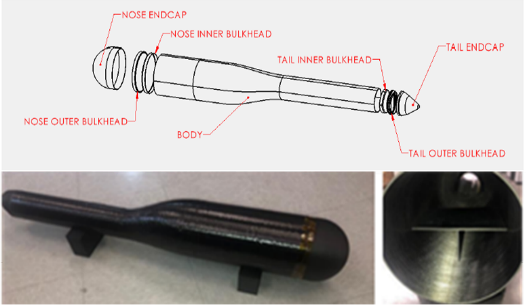
Figure 7. Tube-Launched UAS Test Platform (Source: H. R. Luzetsky).
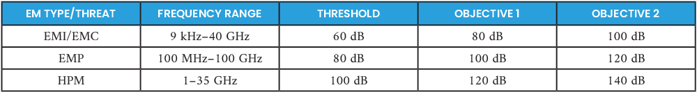
The EM design parameters of the demonstration structure are listed in Table 3. These design requirements provided a threshold and two objective EM shielding effectiveness levels as a function of frequency.
Table 3. EM Shielding Design Parameters for the UAS Demonstrator (Source: H. R. Luzetsky)
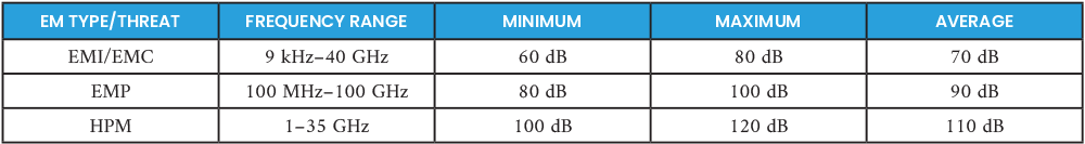
To explore the potential EM shielding, three laminate configurations were constructed for EM shielding evaluation. These configurations were based on the number of incorporated layers of copper mesh that, while meeting the basic requirements, defined the potential EM shielding effectiveness of the UAS laminate with the multifunctional composite. They included no layers, two layers, and four layers of copper mesh. The laminate configurations were determined from flat panel tests designed to characterize the EM shielding properties as applied to the representative tube launched demonstrator structure. The results of the EM shielding tests are provided in Table 4.
Table 4. EM Shielding Summary for the UAS Demonstrator (Source: H. R. Luzetsky)
Conclusions
The application of a multifunctional composite with integrated shielding demonstrated a viable method to enhance the shielding effectiveness of a UAS fuselage structure. A demonstration structure demonstrated threshold reductions in the 50-MHz–18-GHz range of the EM spectrum while not exceeding the weight of the state-of-the-art unshielded fuselage skin. Additional work with this material on a larger fuselage structure demonstrated even higher shielding levels, which are only enhanced further when coupled with internal electronics enclosure structures for internal electrical and electronic modules.
More work is required to explore shielding around perforations in the fuselage structure, such as access panels and installation of sensors and antennas. In addition, variability of the protection level with frequency indicated the potential to customize the EM shielding per frequency. This would provide an opportunity to design windows in the structure to facilitate EM transmission to support sensor and communication transmission at specific frequencies while blocking it at others.
References
- Pastor, E., J. Lopez, and P. Royo. “A Hardware/Software Architecture for UAV Payload and Mission Control.” Department of Computer Architecture, Technical University of Catalonia Castelldefels, (Barcelona), Spain, article in IEEE Aerospace and Electronic Systems Magazine, July 2007.
- U.S. Air Force Civil Engineer Center (AFCEC). “High Altitude Electromagnetic Pulse (HEMP) Effects and Protection.” High Altitude Electromagnetic Pulse (HEMP) Effects and Protection | WBDG – Whole Building Design Guide, updated 7 August 2020.
- Piner, R., D. Motes, and T. Kneen. “Development of EMI Shielding Capabilities of Fiber Reinforced Composites.” DSIAC Technical Inquiry (TI) Response Report, February 2022.
- U.S. Department of Defense. “Electromagnetic Hardened Composite Enclosures for Aircraft Systems.” AF131-110, SURVICE Engineering Company SBIR, 2013.
Biography
Harry R. (“Rick”) Luzetsky is a subject matter expert in composites and survivability at SURVICE Engineering Company’s Aberdeen Research Organization – Research and Analysis Group. He currently supports the U.S. Army Evaluation Center in the survivability assessment of military platforms and has been involved in developing a ballistic-tolerant composite drive shaft, armored actuators, a thermoplastic tail cone, and a multifunctional composite material with structural and integrated electromagnetic shielding capabilities for military platform structures. He has over 40 years of experience with vertical lift aircraft, specializing in composite materials and survivability technology enhancements to improve platform performance. He holds two autonomous, self-sealing, fuel-bladder patents. Mr. Luzetsky holds a B.S. in materials engineering from Drexel University.